Method and apparatus for configurable hardware augmented program generation

Inactive Publication Date: 2003-10-21
KEYSIGHT TECH
View PDF3 Cites 11 Cited by
  • Summary
  • Abstract
  • Description
  • Claims
  • Application Information

AI Technical Summary

Problems solved by technology

Modern electronics systems have become more complex.
As a result, the systems used to test modern electronic systems have also become more complex.
The software hardware configuration is static and typically does not accommodate changes in test patterns or sequences.
On a complex DUT this may create a significant hurdle since first the DUT must be thoroughly understood.
For complex DUT's this may take weeks or months.
However, all of the test routes, the placement of th

Method used


Image

  • Method and apparatus for configurable hardware augmented program generation
  • Method and apparatus for configurable hardware augmented program generation
  • Method and apparatus for configurable hardware augmented program generation

Examples


Embodiment Construction

While the present invention is described herein with reference to illustrative embodiments for particular applications, it should be understood that the invention is not limited thereto. Those having ordinary skill in the art and access to the teachings provided herein will recognize additional modifications, applications, and embodiments within the scope thereof and additional fields in which the present invention would be of significant utility.

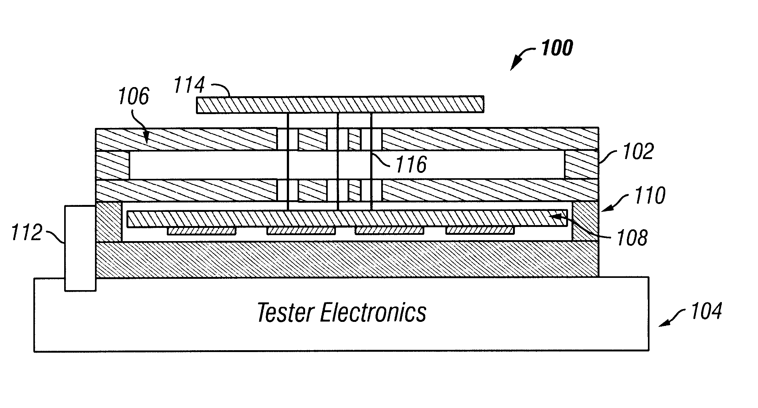
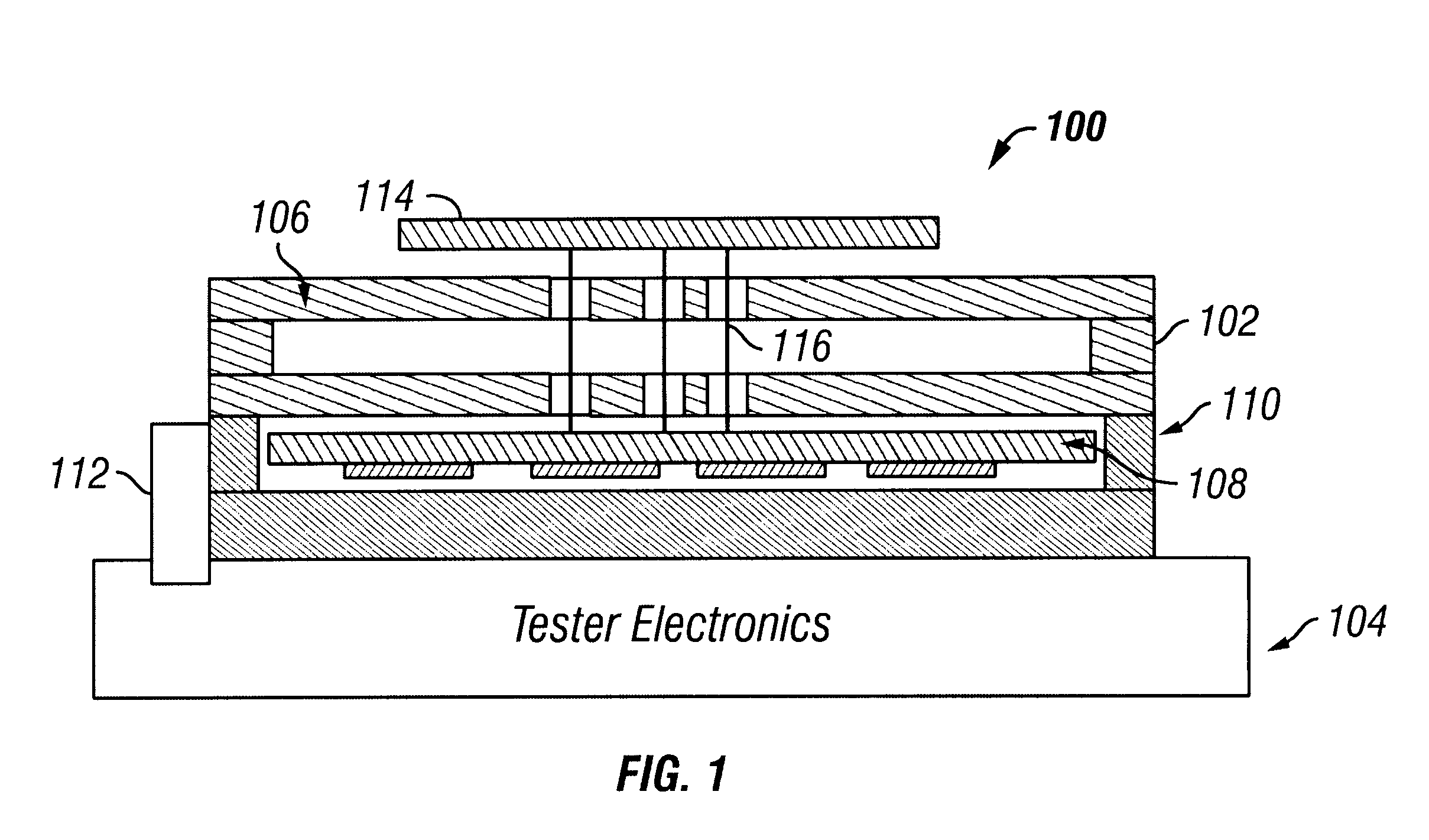
FIG. 1 displays an electronic testing system 100. The electronic testing system 100 includes a fixture assembly 102 and tester electronics 104. The fixture assembly 102 provides structural alignment for a device under test (DUT). The tester electronics 104 provides automatic test functionality such as signal pattern generation, receipt and analysis.

The fixture assembly 102 includes a prototype adapter assembly 106 positioned above a support assembly 110. The support assembly 110 provides support for the adapter assembly 106 and houses a tes...


PUM


Abstract

A method and apparatus are disclosed for enabling reconfiguration of a test system. The test system includes an adapter assembly and a tester electronics assembly. The adapter assembly includes two probe plates, which hold a probe field. The two probe plates include a plurality of holes extending through each probe plate. Each hole includes a flange area for accommodating deflection of the probes, inserted in the holes extending through the probe plates. The flange area and the use of flexible probes facilitate a deflection and an offset of the probes in the probe plates. A tester assembly includes a plurality of wear pads on the topside of a printed circuit board. The wear pads positioned to engage the bottom end of the probes. Configurable logic elements located on the underside of the printed circuit board are used to generating and receive test-signals, depending on where the probes make contact with the wear pads on the printed circuit board.

Description

1. Field of the InventionThis invention relates to electronic test systems. Specifically, the present invention relates to configurable electronic test systems.2. Description of the Related ArtModern electronics systems have become more complex. As a result, the systems used to test modern electronic systems have also become more complex. Conventional digital electronics are deployed in printed circuit boards (PCB) or integrated circuits. These printed circuit boards and integrated circuits include millions of digital components such as logical gates, memories such as latch arrays, etc. In addition, the electronic systems include millions of connections between the components to communicate signals. The connection between two components is referred to as a trace.Test systems are used to test conventional printed circuit boards and integrated circuits. These test systems typically include an interface, known as a fixture, for interfacing with a device under test (DUT). In addition, t...

Claims


Application Information

Patent Timeline
IPC IPC(8): G01R1/073
CPCG01R1/07371
Inventor CROOK, DAVID TMCDERMID, JOHN ELLIOTT
Owner KEYSIGHT TECH
Why Eureka
Try Eureka