Filter-cleaning device and method, and fluid pulse generator particularly useful therein

a filter and fluid pulse technology, applied in the direction of filtration separation, auxillary pretreatment, separation processes, etc., can solve the problems of expensive production and maintenance, jet cleaning devices, and ineffective filter cleaning, etc., to achieve the effect of cleaning filters thoroughly and efficiently

Inactive Publication Date: 2003-11-04
GIDEON ROSENBERG D B A ITEC +1
View PDF12 Cites 47 Cited by
  • Summary
  • Abstract
  • Description
  • Claims
  • Application Information

AI Technical Summary

Benefits of technology

An object of the present invention is to provide a novel filter-cleaning device which is capable of thoroughly and efficiently cleaning filters, particularly the air-type disc filters, but also other types of compressible fluid filters. Another object of the invention is to provide a method of cleaning filters; and a still further object of the invention is to provide a novel compressible fluid pulse generator particularly useful in cleaning the filters, but capable of use in other applications.

Problems solved by technology

Such pulse jet cleaning devices, are therefore not effective in thoroughly cleaning the filter body, and moreover are relatively expensive to produce and to maintain.

Method used


Image

  • Filter-cleaning device and method, and fluid pulse generator particularly useful therein
  • Filter-cleaning device and method, and fluid pulse generator particularly useful therein
  • Filter-cleaning device and method, and fluid pulse generator particularly useful therein

Examples


Embodiment Construction

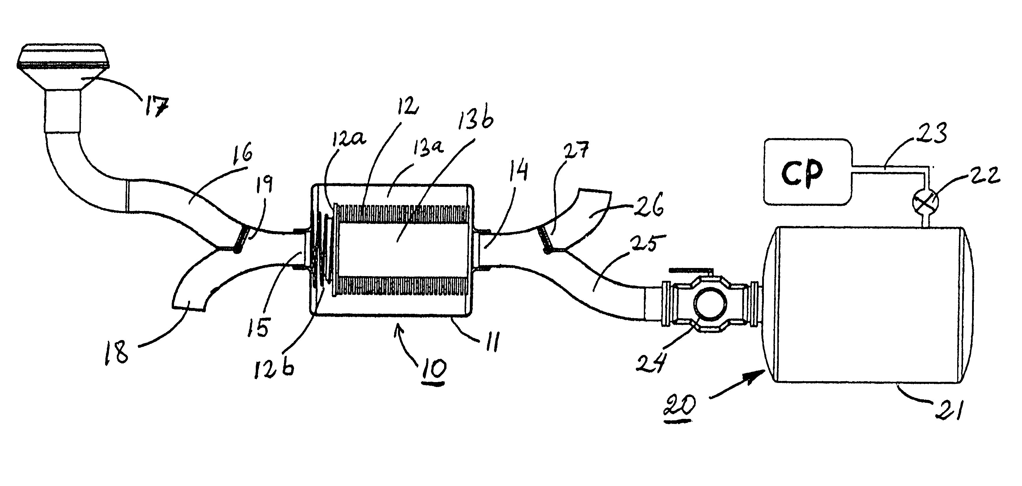
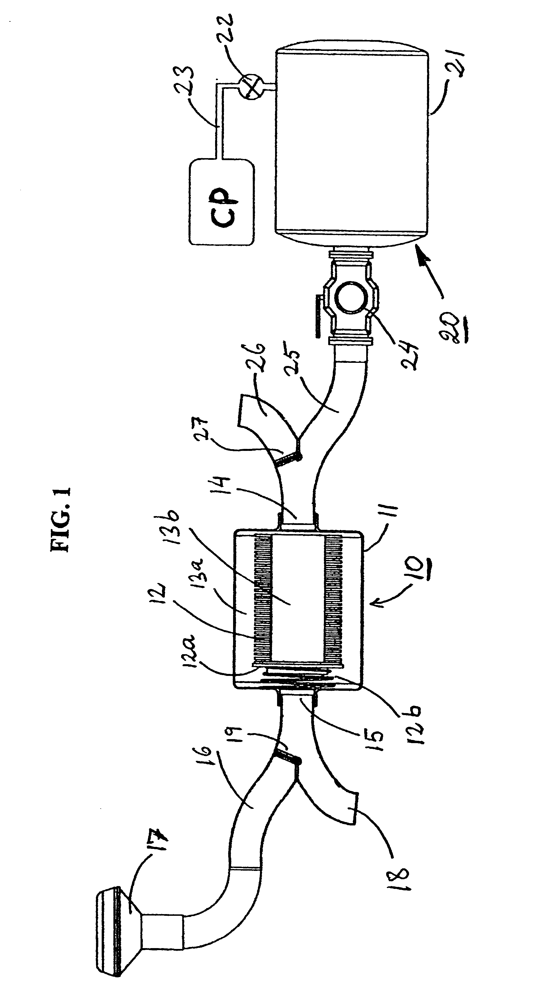
For purposes of example, the invention is described below with respect to the disc-type air filter illustrated in U.S. Pat. No. 5,797,978, generally designated 10 in FIG. 1. Such a filter includes a housing 11 containing a filter body in the form of a stack of annular discs 12 having ribbed side faces defining a plurality of filtering paths leading from an outer passageway 13a defined by the outer edges of the discs radially inwardly to a central passageway 13b defined by the inner edges of the discs. The inner passageway is connected to an outlet 14 for the filtered air introduced via an inlet 15.

The stack of discs 12 further includes an end disc 12a at the inlet end of the stack closing the inner passageway 13b, and urged against the other discs by a spring 12b. Further details of the construction and operation of such a disc filter appear in the above-cited patents incorporated herein by reference.

The inlet 15 is in the form of a duct having one branch leading to a cyclone or oth...


PUM

PropertyMeasurementUnit
pressureaaaaaaaaaa
pressureaaaaaaaaaa
inner diameteraaaaaaaaaa

Abstract

A filter-cleaning device and method for cleaning a filter (10) utilizing a compressible fluid pulse generator (20) including a pressure tank (21), a tank inlet (23) for inletting pressurized air or other compressible fluid, and a valve member (24) normally in a closed position closing the tank outlet (28), but being openable in a quick-action manner to produce a high-pressure high-flow impulse of fluid applied via the tank outlet to the filter outlet to back-flush the filter.

Description

FIELD AND BACKGROUND OF THE INVENTIONThe present invention relates to a cleaning device and method for cleaning air or other compressible fluid filters, and also to a compressible fluid pulse generator useful in such cleaning devices and methods. The invention is particularly useful for cleaning, by back flushing, disc-type filters such as described in U.S. Pat. Nos. 5,797,978; and 4,661,250, the disclosures in which patents are hereby incorporated by reference. The invention is therefore described below for use in cleaning such disc-type filters, but it will be appreciated that the invention could also be used for cleaning other types of filters, and also for producing high-pressure compressible fluid pulses for other applications.Many filters generally, and disc-type filters in particular, may be cleaned by back-flushing, i.e., by introducing a pressurized fluid through the filter outlet to back-flush the filter body through the filter inlet. When the filter is used for filtering ...

Claims


Application Information

Patent Timeline
Patent Type & Authority Patents(United States)
IPC IPC(8): B01D46/24B01D29/66B01D41/04B01D46/00
CPCB01D41/04B01D46/2411B01D46/0068B01D46/0058B01D29/66B01D46/90B01D46/71
Inventor ROSENBERG, GIDEON
Owner GIDEON ROSENBERG D B A ITEC
Why Eureka
Try Eureka