Time keeping apparatus and control method therefor

a timekeeping apparatus and time control technology, applied in the field of time keeping apparatus and control method therefor, can solve the problems of inability to know the correct time for several minutes, inaccurate time display, and drawbacks of radio-controlled watches

Inactive Publication Date: 2003-11-04
SEIKO EPSON CORP
View PDF7 Cites 26 Cited by
  • Summary
  • Abstract
  • Description
  • Claims
  • Application Information

AI Technical Summary

Problems solved by technology

However, the radio-controlled watch has a drawback.
The drawback is that when a user wears the watch that was left unused (not worn on a user's arm) for a long time, the user cannot know the correct time for several minutes.
This is also because there are cases where the watch does not conduct a time adjustment, but continues to perform a time display: one such case is when the storage or storage unit voltage declines below a certain voltage where time display can become incorrect.
When the stored voltage exceeds the withstand pressure voltage, the storage unit enters a state of overcharge and the quality of the storage unit deteriorates.

Method used


Image

  • Time keeping apparatus and control method therefor
  • Time keeping apparatus and control method therefor
  • Time keeping apparatus and control method therefor

Examples


first embodiment

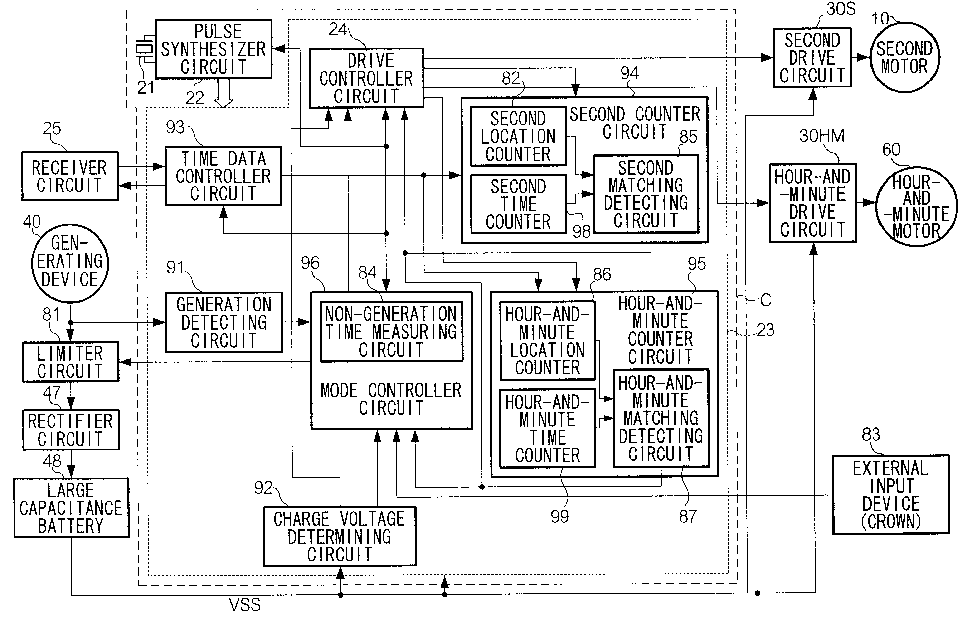
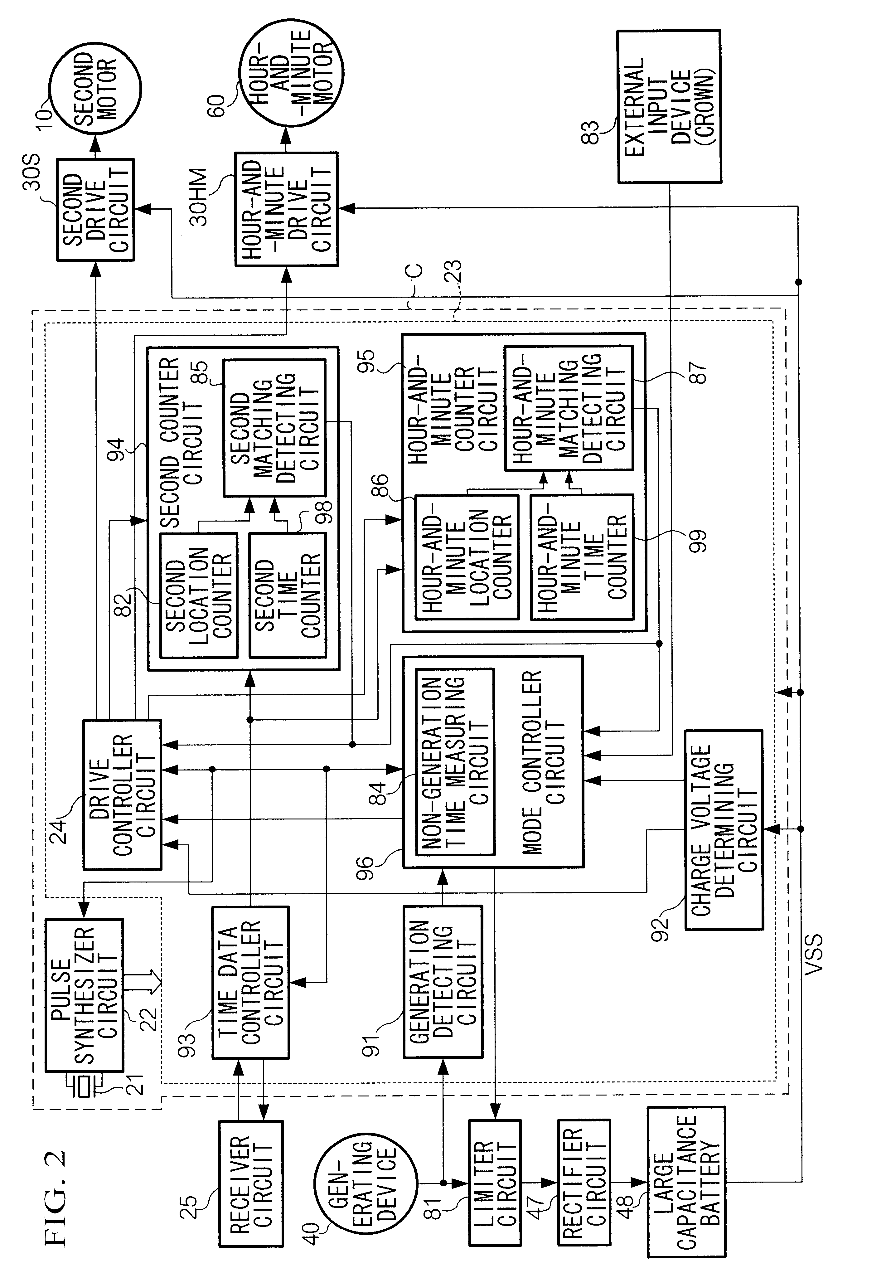
As explained above, by the present invention, even during the power saving mode, the time data is periodically received and is set to the counted values of the hour-and-minute time counter 99 and the second time counter 98. So when switching from the power saving mode to the display mode, it is possible to display the correct time without receiving the time data yet again.

second embodiment

[2] Second Embodiment

In contrast to the first embodiment of the present invention, in which the actual location of the hands is not determined, a second embodiment of the present invention has a mechanism by which actual locations of the hands are determined in order to perform a current time display correctly when switching from the power saving mode to the display mode.

[2.1] Configuration of the Second Embodiment

FIG. 6 shows a configuration of a hand location determining element assembled in the hand movement mechanism of the time keeping apparatus of the second embodiment of the present invention. For the sake of easy understanding of the configuration of the hand location determining element, in FIG. 6, the hour hand, the minute hand, and the second hand are configured to be driven by one drive motor. The time keeping apparatus of the second embodiment of the present invention has the same configuration as the first embodiment shown in FIGS. 1 and 2 except that the second embodi...

third embodiment

[3] Third Embodiment

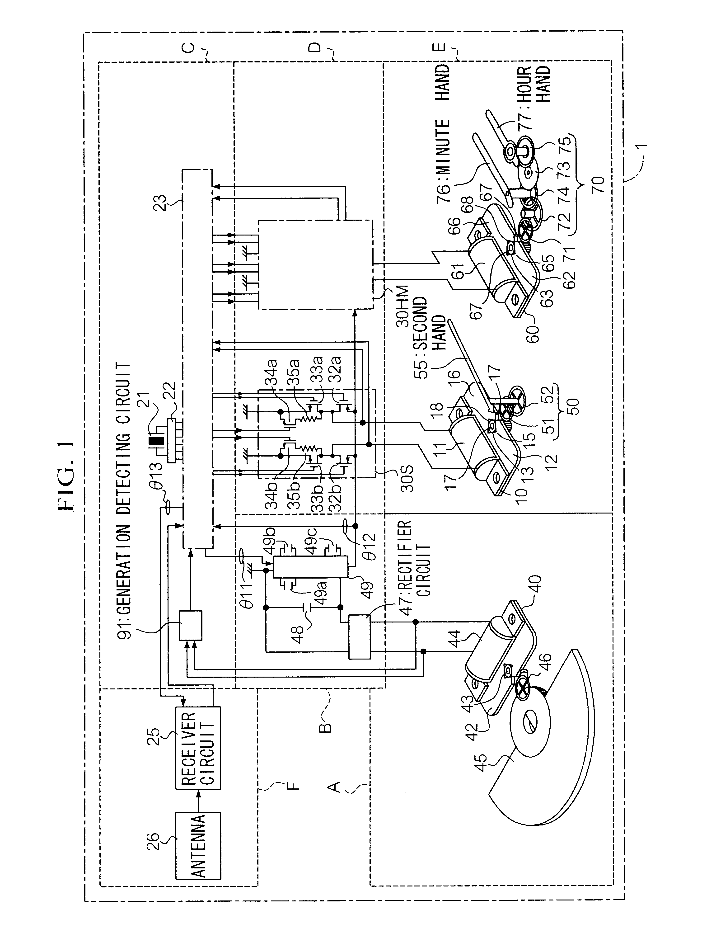
In the third embodiment of the present invention, a solar cell is used for the power generation unit A. In FIG. 11, a schematic configuration of a time keeping apparatus of the third embodiment of the present invention is shown. In FIG. 11, each part identical to that in FIG. 1 has the same symbol as in FIG. 1, so its detailed explanation is omitted. The time keeping apparatus of the third embodiment of the present invention comprises a standard oscillation source 21, a controller circuit 23, a receiver circuit 25, a drive circuit 30, a countercurrent prevention diode 41, a large capacitance capacitor (battery or storage unit) 48, a limiter circuit 81, a solar cell 89, and a generation detecting circuit 91". The solar cell 89 converts light energy into electric energy. The countercurrent prevention diode 41 is used to prevent the stored charge in the storage unit 48 from flowing back.

With reference to FIG. 12, operation of the generation detecting circuit 91" wil...


PUM


Abstract

When a time keeping apparatus is in a power saving mode, performing time display is stopped, and the apparatus periodically receives external time data and sets the data into a second time counter and an hour-and-minute time counter. When the operation mode of the time keeping apparatus is switched from the power saving mode to the display mode, the apparatus resumes display of the current time based on the counted values in the second time counter and the hour and minute time counter.

Description

1. Field of the InventionThe present invention relates to a time keeping apparatus and a control method therefor, and more particularly to a radio-controlled timepiece having a power saving function to reduce its power consumption.2. Description of the Related ArtA radio-controlled watch that has a power saving function and receives external time data (i.e. time signals received from outside the watch) and adjusts the time is disclosed in Japanese Patent Application Laid Open Publication No. 11-223684 entitled "radio-controlled watch". The radio-controlled watch has a thermoelectric generator that generates electricity by using a temperature difference between the wearer's arm and outside air. The watch stores the electricity in its storage unit and uses the electricity to operate.The radio-controlled watch periodically receives a standard time radio signal from the Communications Research Laboratory (CRL) of Japan that is transmitted at a frequency of 40 kHz under a call sign of JJ...

Claims


Application Information

Patent Timeline
Patent Type & Authority Patents(United States)
IPC IPC(8): G04G19/00G04G19/08G04G19/12G04C3/14G04C3/00G04C10/04G04G5/00G04G19/02G04G99/00G04R20/00
CPCG04G19/12G04G19/08
Inventor FUJISAWA, TERUHIKO
Owner SEIKO EPSON CORP
Why Eureka
Try Eureka