Reinforcing system for a door frame

a reinforcement system and door frame technology, applied in the direction of frame fastening, window/door frame, warlike protection, etc., can solve the problems of design, material easily splintered and broken through, and nothing to solv

Inactive Publication Date: 2003-11-25
CAMPERELLI JAMES A
View PDF25 Cites 25 Cited by
  • Summary
  • Abstract
  • Description
  • Claims
  • Application Information

AI Technical Summary

Problems solved by technology

This material is easily splintered and broken through with only a moderate amount of force directed against the door adjacent the locking mechanism.
However, such designs do nothing to solve the problem of the doorjamb being splintered when the door is kicked adjacent the door latch or lock.
Although such designs do provide additional reinforcement, they are not capable of forming part of a fully integrated system that provides for reinforcement for all sections of the door frame.
Although there are some prior art systems such as seen in U.S. Pat. No. 4,295,299 that teach using a reinforcing plate wrapped partially around the doorjamb that can extend the height of the doorjamb, there are no reinforcement plates that are designed to the twisting forces incurred at the top and bottom corners of a door frame when a person attempts to kick in the door.

Method used


Image

  • Reinforcing system for a door frame
  • Reinforcing system for a door frame
  • Reinforcing system for a door frame

Examples


Embodiment Construction

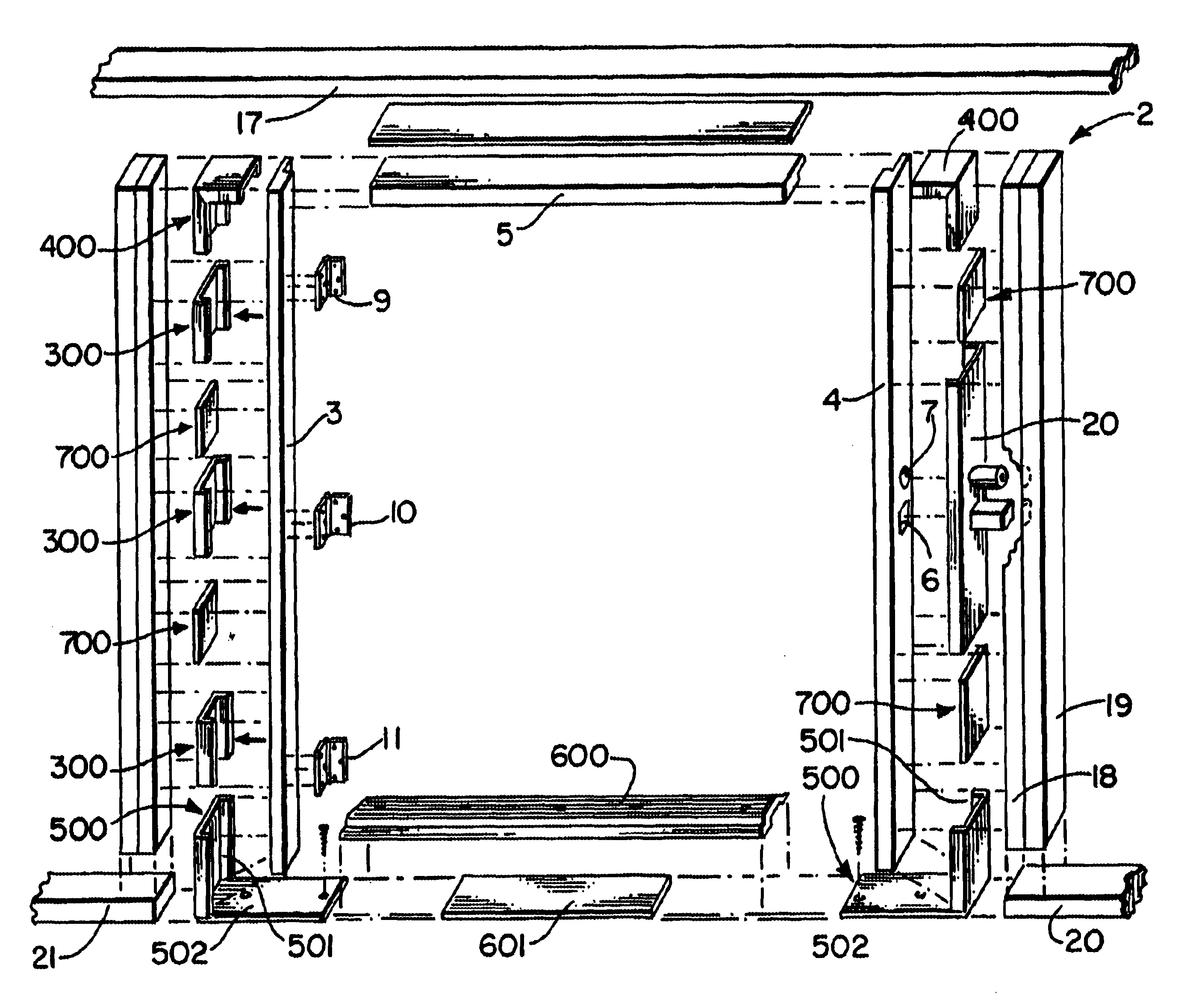
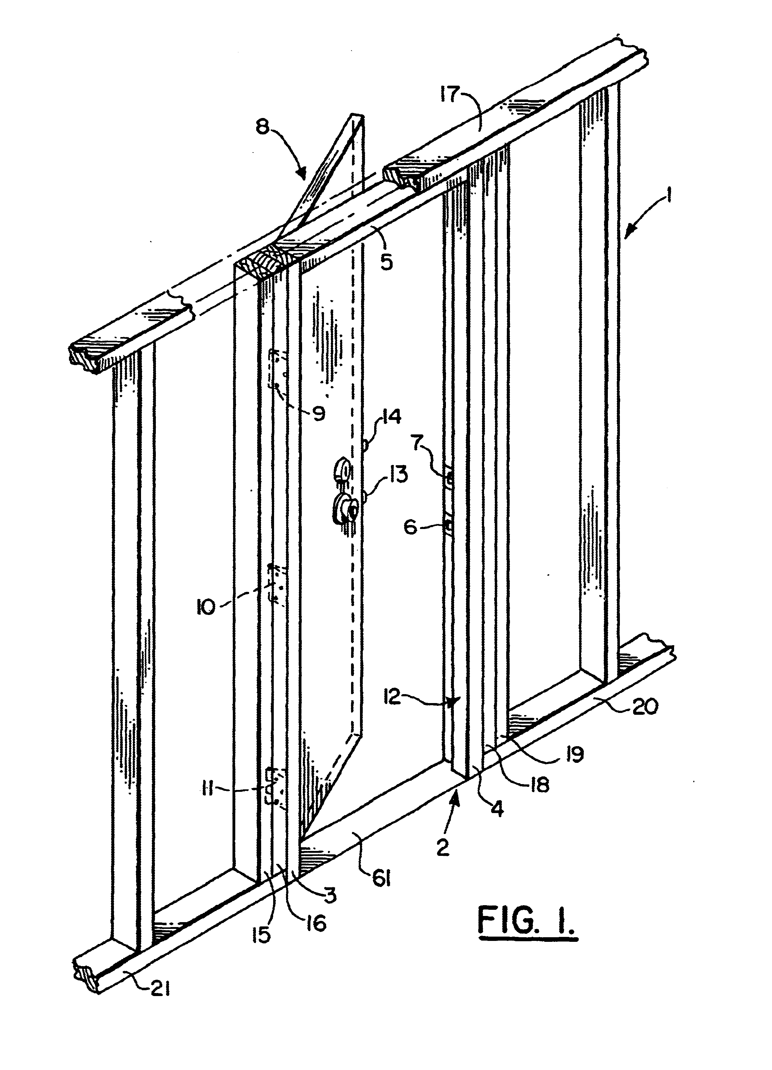
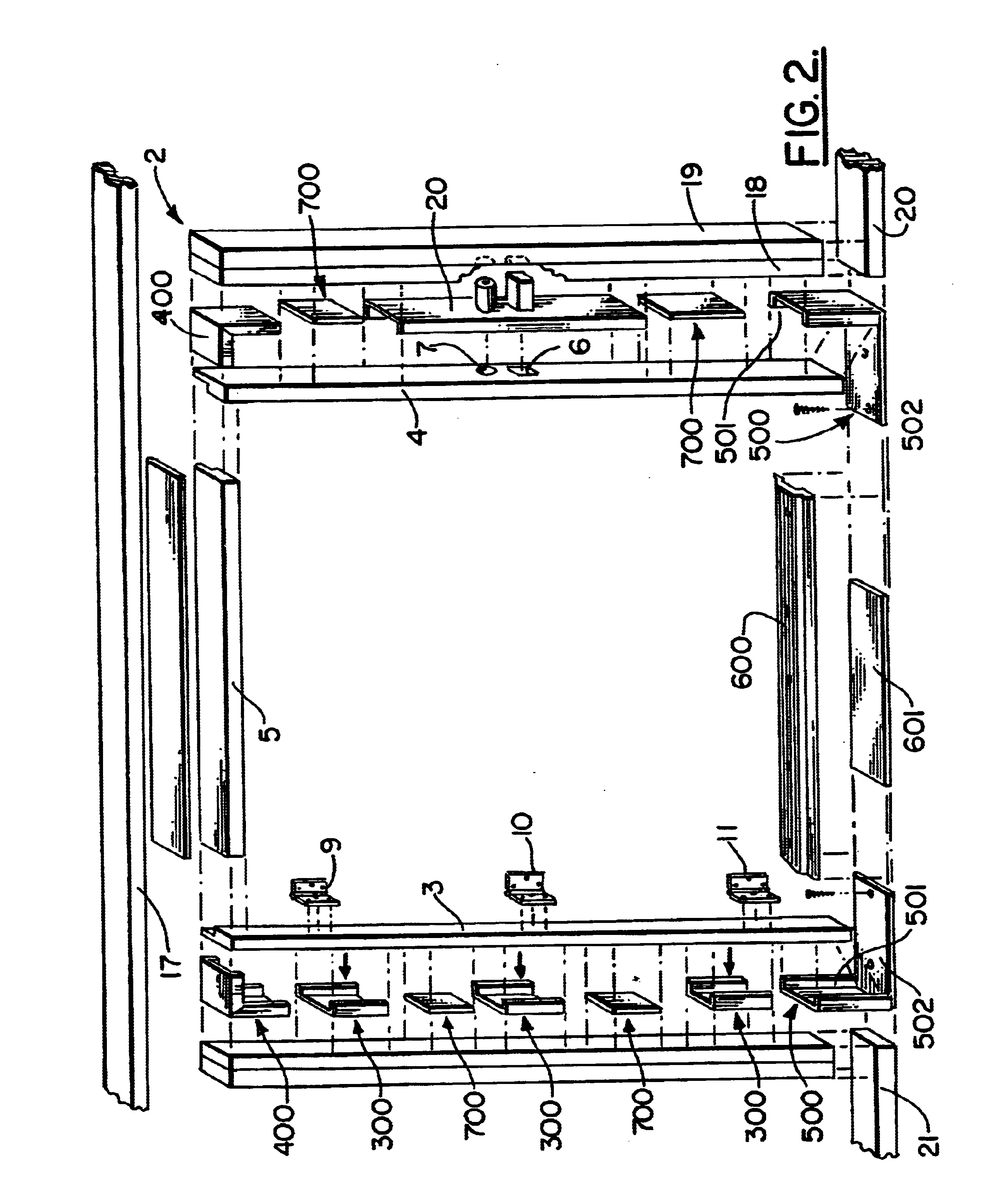
Without any intent to limit the scope of this invention, reference is made to the figures in describing the preferred embodiments of the invention. Referring to FIG. 1 a cutaway partial view of a typical wall 1 having a conventional door frame 2 forming a door way is illustrated. The door frame 2 includes two vertical doorjamb members 3, 4 and one upper horizontal doorjamb member 5 that separates the vertical doorjamb members 3, 4 to form threshold 61. One of the vertical doorjamb members 3 is provided with a latch opening 6 and a lock opening 7. A door 8 will be pivotly connected by hinge assemblies 9, 10, and 11 to vertical doorjamb 4 in a manner to permit the door to shut against jamb 12 of doorjamb member at a position aligning the door latch 13 and door lock 14 with the latch opening 6 and lock opening 7, respectively. The doorjamb members 3, 4 and 5 will typically be nailed to wall studs 15-19 that are attached vertically to floor plate members 20 and 21, as shown. In order to...


PUM


Abstract

A reinforcing system for strengthening a door frame having two parallel vertical doorjambs separated from one another by a top horizontal doorjamb. The reinforcing system comprises two elongated channel-shaped 90° corner members positioned in the upper opposite corners of the door frame. Each corner member comprises one elongated flat panel with two substantially parallel sides extending along and outward from the opposite edges of the flat panel. The flat panel has a width and the parallel sides extend in a direction permitting each of the parallel sides to be positioned adjacent one of the opposing sides of a doorjamb when the flat panel is positioned adjacent the exterior side of the doorjamb. The reinforcing system further comprises at least one elongated straight channel-shaped member otherwise similarly formed positioned on the doorjamb opposite where the door hinges will be attached. The reinforcing system further comprises a strike having a tubular body extending substantially perpendicular from its plate and into an opening through the doorjamb and into the wall stud to which the doorjamb is attached. The tubular body is closed at the extending end by an end plate having an opening shaped to permit a screw, nail or other similar attaching member to extend into the structural member to fix the tubular body to the wall stud.

Description

1. Field of the InventionThis invention relates in general to door frame structures, and in particular to reinforcing plates and banding systems utilized in the construction of lock strikes, door jam plates and framing forming part of a door frame.2. Prior ArtIt has long been recognized that a door mounted in a conventional door frame, even when dead bolted, offers little deterrence to a person who attempts to kick in the door to gain entrance to the building. Typically, external doors are mounted to the doorjamb by at least a pair of hinges and are provided with a latch and dead bolt lock that is extended into a recess provided in the jamb to secure the door in a closed position. The weakest region of a doorframe is the region where the bolt interacts with the doorjamb. The portion of the jamb that is provided for restraining the door bolt or latch generally measures only in fractions of inches and is commonly composed of wood. This material is easily splintered and broken through ...

Claims


Application Information

Patent Timeline
Patent Type & Authority Patents(United States)
IPC IPC(8): E05B15/00E06B1/52E06B1/56E05B15/02E06B1/60E06B5/11E06B5/10
CPCE05B15/0205E06B1/52E06B1/6092E06B1/6015E06B5/11
Inventor CAMPERELLI, JAMES A.
Owner CAMPERELLI JAMES A
Why Eureka
Try Eureka