Image forming apparatus, image bearing member life detecting method, and process cartridge detachably attachable to image forming apparatus

a technology of image bearing member and process cartridge, which is applied in the direction of electrographic process apparatus, instruments, optics, etc., can solve the problems of high cost, and poor precision of photosensitive drum li

Inactive Publication Date: 2003-11-25
CANON KK
View PDF18 Cites 27 Cited by
  • Summary
  • Abstract
  • Description
  • Claims
  • Application Information

AI Technical Summary

Problems solved by technology

In this case, however, the life of the photosensitive drum is detected with poor precision.
Also when the number of image forming sheets is merely integrated, the life of the photosensitive drum is detected with poor precision because the rotation period of the photosensitive drum per recording medium changes depending on the number of image forming sheets per job, i.e., the successive number of recording media for forming an image after the start of image forming operation, and the life of the photosensitive drum (to be described later) changes depending on the rotation period.
Practicing this method, however, requires a surface potential sensor and an electrical circuit for processing an output from the sensor, resulting in high cost.
The detection ability is poor for a partial error, and the stability is low due to variations or changes over time in the surface potential sensor.
The life of the photosensitive drum is not always accurately detected.
The number of image forming sheets is integrated, and when the assured life of the electrophotographic photosensitive member has expired, the apparatus stops and cannot be used.
However, the operation based on the toner amount in the recovery toner vessel functions when toner replenishment is frequently done because of an extremely high image density and the recovery toner vessel will become full earlier than the assured life (assured number of sheets) of the electrophotographic photosensitive member.
The roller electrostatic charging apparatus has difficult problems: the roller resistance must be adjusted to obtain uniform electrostatic charge, drum contamination by bleed from rubber which forms the roller must be prevented, strict constraints are posed on the roller shape and surface property in order to obtain uniform electrostatic charge.
However, contact electrostatic charge greatly damages the electrophotographic photosensitive member, compared to corona electrostatic charge.
Even in the same contact electrostatic charge method, the damage to the electrophot...

Method used


Image

  • Image forming apparatus, image bearing member life detecting method, and process cartridge detachably attachable to image forming apparatus
  • Image forming apparatus, image bearing member life detecting method, and process cartridge detachably attachable to image forming apparatus
  • Image forming apparatus, image bearing member life detecting method, and process cartridge detachably attachable to image forming apparatus

Examples


first embodiment

A life detecting method of detecting the life of a photosensitive drum 1 in the first embodiment will be described.

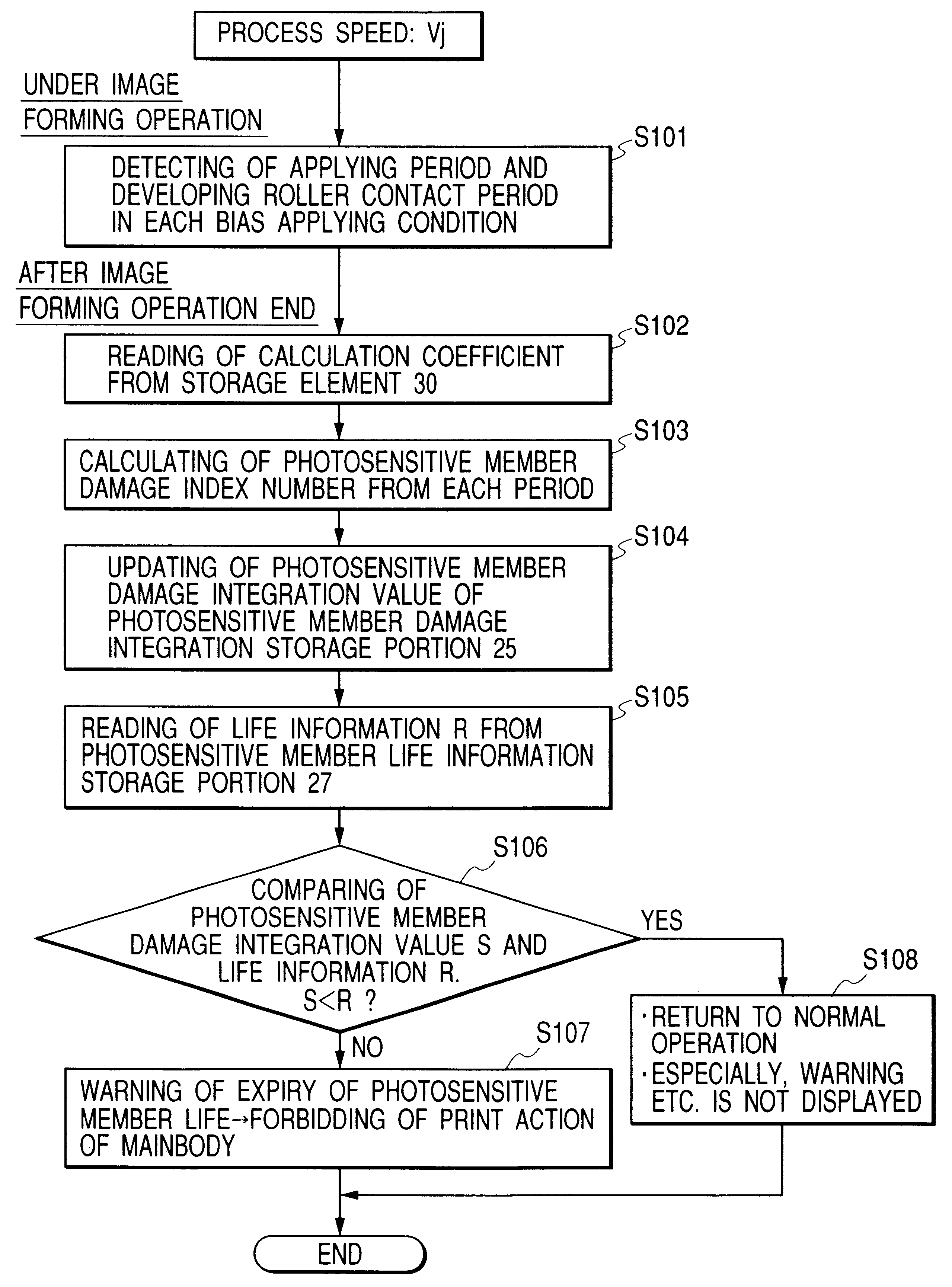
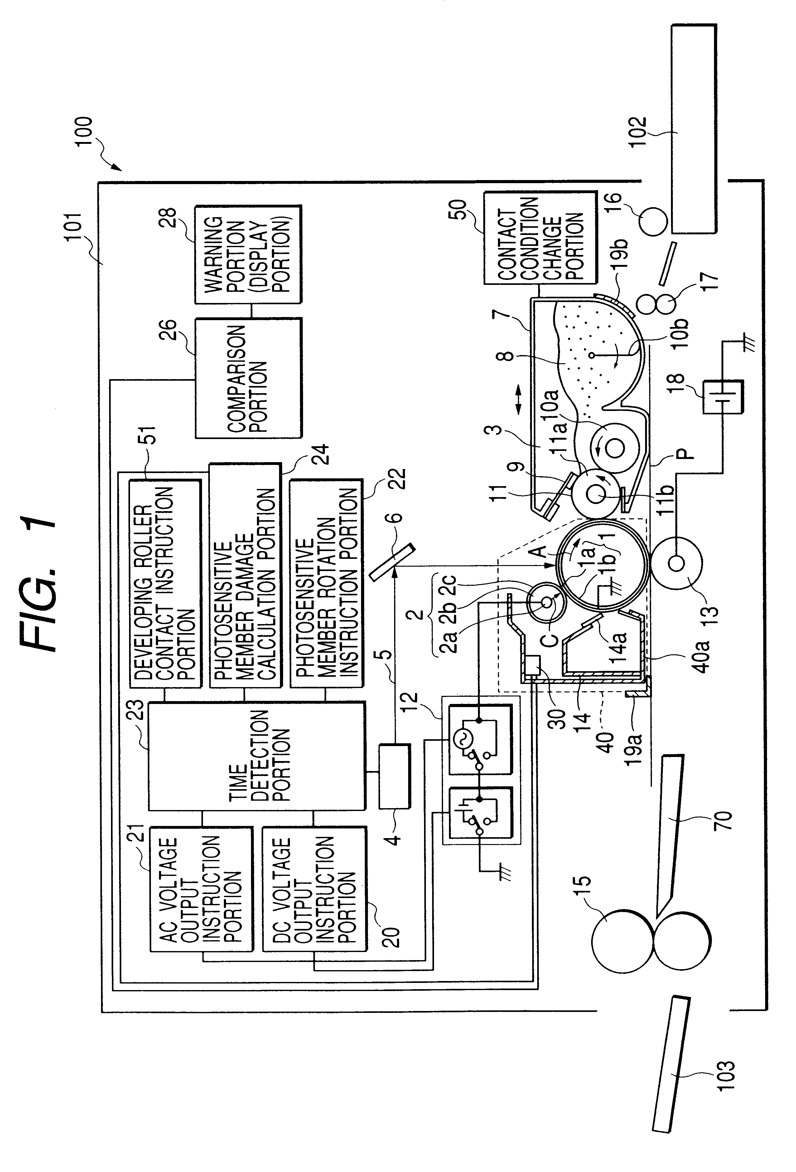
FIG. 5 is a flow chart showing the life detecting method in the first embodiment. During one job of image forming operation, a time detection portion 23 detects applying periods t1, t2, and t3 under each electrostatic charge bias applying condition, and a period td during which a developing roller 11 is in contact with the photosensitive drum 1 (step S101).

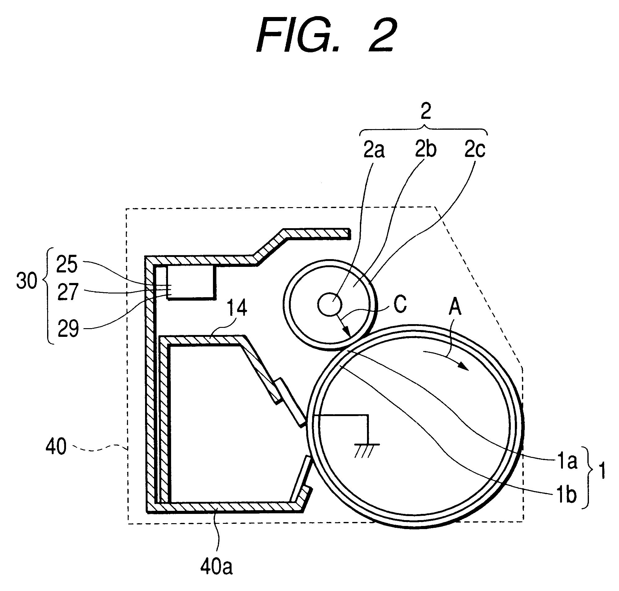
After one job of image forming operation ends, photosensitive member damage calculation coefficients k1j, k2j, k3j, and kdj stored in a photosensitive member damage calculation coefficient storage portion 29 of a storage device 30 in a drum unit 40 are sent to a photosensitive member damage calculation portion 24 in correspondence with the applying periods t1, t2, and t3, the developing roller contact period td, and a process speed Vj under each electrostatic charge bias applying condition (step S102). The photosensit...

second embodiment

The second embodiment sets two pieces of information for determining the life of the photosensitive drum 1. More specifically, in the second embodiment, a storage device 30 in a drum unit 40 incorporates a photosensitive member life information storage portion 27. The photosensitive member life information storage portion 27 stores two pieces of information: warning information Y for reminding the user to prepare for replacement when the life of the photosensitive drum 1 will expire soon, and actual photosensitive member life information R. The warning information Y and photosensitive member life information R have a relation: warning information Y

FIG. 6 is a flow chart showing the life detecting method in the second embodiment. Steps S201 to S204 shown in FIG. 6 are identical to steps S101 to S104 in the first embodiment shown in FIG. 5, and a description thereof will be omitted.

After one job of image forming operation ends and updating of ...

third embodiment

The third embodiment sets two pieces of information for determining the photosensitive drum life, similar to the second embodiment. In the third embodiment, these pieces of information are warning information Y for reminding the user to prepare for replacement when the life of the photosensitive drum 1 will expire soon, and actual photosensitive member life information R. The warning information Y and photosensitive member life information R have a relation: warning information Y

In the third embodiment, a photosensitive member life information storage portion 27 of a storage device 30 in a drum unit 40 stores photosensitive member life selection information J, instead of the warning information Y and life information R. The photosensitive member life selection information J is made up of, e.g., 10 pieces of photosensitive member life selection information J in a photosensitive member life information table shown in Table 1. The respective pi...


PUM


Abstract

An image bearing member life detecting method capable of accurately detecting that the life of an image bearing member has expired or will expire soon, an image forming apparatus using the method, and a cartridge detachably attachable to the image forming apparatus, are provided. An image bearing member damage index number D representing the consumption degree of an image bearing member is calculated on the basis of an applying period under each condition of an electrostatic charge bias applied to an electrostatic charging portion for forming an electrostatic latent image on the image bearing member, and/or the contact period of a developing portion for developing the electrostatic latent image on the image bearing member. When the process speed is switched, the calculation method is switched in accordance with the process speed, and the image bearing member damage index number D is calculated. The image bearing member damage index number D is integrated and stored as an image bearing member damage integration value S. The image bearing member damage integration value S is compared with life information R corresponding to the image bearing member damage integration value S for a predetermined life of the image bearing member, thereby detecting the life of the image bearing member.

Description

1. Field of the InventionThe present invention generally relates to an image forming apparatus for forming an electrostatic latent image on an electrophotographic photosensitive member by electrophotography and visualizing the electrophotographic latent image with a developer, an image bearing member life detecting method, and a process cartridge detachably attachable to the image forming apparatus.The electrophotographic image forming apparatus includes, e.g., an electrophotographic copying machine, electrophotographic printer (e.g., LED printer or laser beam printer), and electrophotographic facsimile apparatus.The cartridge detachably attachable to the main body of the electrophotographic image forming apparatus means a cartridge having at least one of an electrophotographic photosensitive member, an electrostatic charging means for electrostatically charging the electrophotographic photosensitive member, a developing means for supplying a developer to the electrophotographic pho...

Claims


Application Information

Patent Timeline
IPC IPC(8): G03G21/18G03G21/00
CPCG03G21/1889G03G2221/1823G03G2221/1663G03G2215/021
Inventor MATSUGUMA, MINORU
Owner CANON KK
Why Eureka
Try Eureka