Pyrotechnic igniter arrangement with integrated mechanically decoupled electronic assembly

a technology of electronic assembly and igniter, which is applied in the direction of ammunition fuzes, blasting cartridges, weapons components, etc., can solve the problems that the arrangement or substrate cannot be used for both the ignition/pyrotechnic zone and the one-piece carrier arrangement as well, and does not provide a comparably effective protection for the electronic assembly

Inactive Publication Date: 2003-12-09
CONTI TEMIC MICROELECTRONIC GMBH
View PDF36 Cites 11 Cited by
  • Summary
  • Abstract
  • Description
  • Claims
  • Application Information

AI Technical Summary

Benefits of technology

The basic idea of the invention is to provide a decoupling location or feature for mechanically decoupling the portion of the carrier arrangement located in the pyrotechnic zone from the rest of the carrier arrangement. This is achieved, as mentioned above, by reducing the strength or stiffness of the carrier arrangement in this decoupling location, so that the decoupling location will break, yield or flex in the event of a mechanical load exceeding a prescribed maximum load threshold being applied thereto. The decoupling location can, for example, be embodied as a frangible link feature, i.e. an intended breaking location, or as an intended flexing or bending location, or as a meltable soldered connection.
With the inventive features, it is not necessary to avoid the structural separation of the electronic zone and the pyrotechnic zone, for example by a protective wall therebetween, yet the invention still provides a simple carrier arrangement in common for the electronic assembly in the electronic zone as well as for the ignition bridge in the pyrotechnic zone. In a particular embodiment, the ignition bridge extends through a protective wall provided between the electronic zone and the ignition zone. The carrier arrangement is simply provided with one or more decoupling locations, which mechanically decouple the portion of the carrier arrangement located in the electronic zone from the portion located in the pyrotechnic zone, after ignition of the pyrotechnic charge or active mass, i.e. after the actual ignition pulse has been applied to the ignition bridge, yet preferably during the burning of the pyrotechnic charge. Thereby, the mechanical decoupling feature at the decoupling location prevents the further transmission of mechanical loads exceeding the prescribed acceptable load threshold level from the pyrotechnic zone to the electronic zone.

Problems solved by technology

A one-piece carrier arrangement or substrate cannot be used for both the ignition / pyrotechnic zone as well as the electronic zone, because of their physical separation by the protective wall.
However, such simple carrier arrangements do not provide a comparably effective protection for the electronic assembly against the effects of pressure, temperature, or forces that arise during the triggering or ignition of the igniter arrangement.
This can be disadvantageous, if the pressure, temperature, forces, or other mechanical influences arising from the pyrotechnic zone in turn are transmitted to the electronic assembly and lead to a disruption thereof.

Method used


Image

  • Pyrotechnic igniter arrangement with integrated mechanically decoupled electronic assembly
  • Pyrotechnic igniter arrangement with integrated mechanically decoupled electronic assembly

Examples


Embodiment Construction

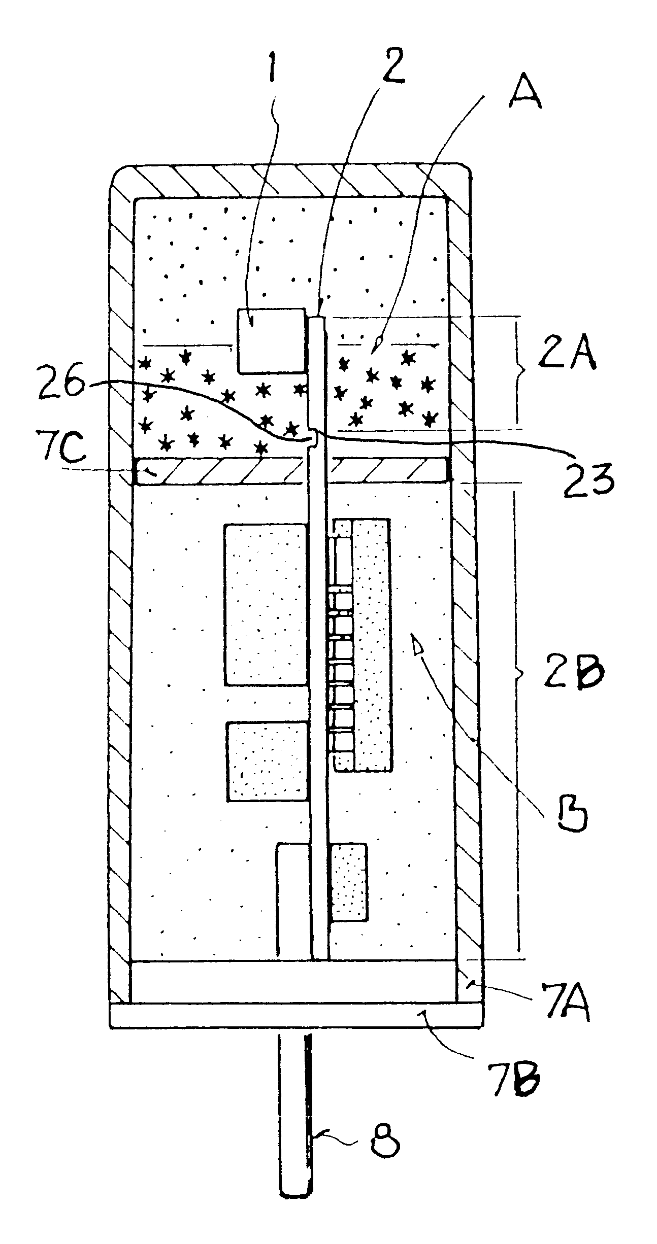
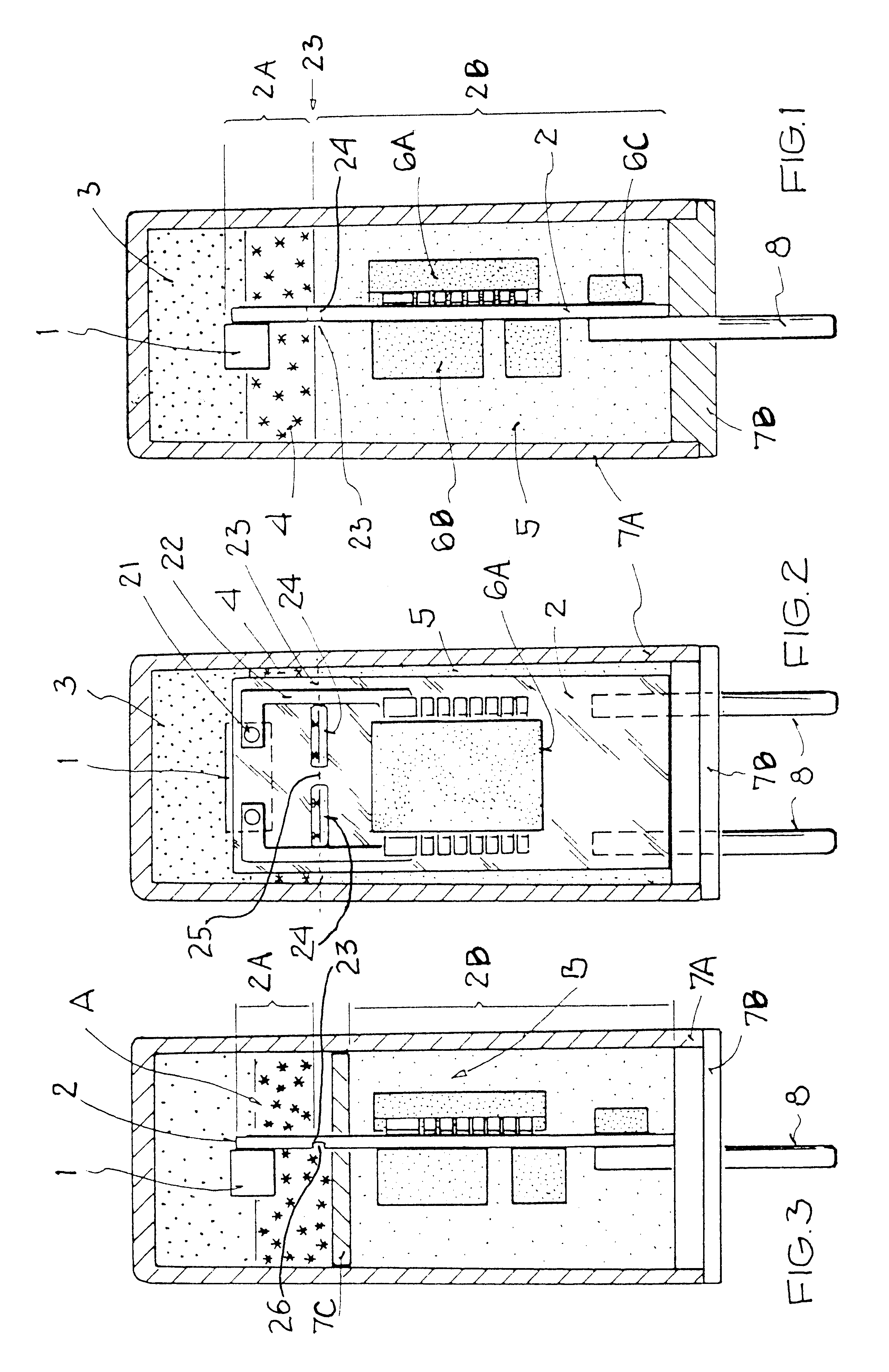
FIG. 1 shows an especially preferred embodiment of an igniter arrangement which may, for example, be used as the igniter for a gas generator of a passenger or occupant protection device, e.g. an airbag, in a motor vehicle. The igniter arrangement comprises a two-part housing 7A, 7B including a housing cannister 7A and a housing lid 7B, a carrier arrangement or substrate 2, an ignition bridge 1 arranged on and electrically connected with the carrier arrangement 2, a pyrotechnic charge or active mass 3 arranged and adapted to be ignited by the ignition bridge 1, and an electronic assembly 6A, 6B, 6C, including various electronic components 6A, 6B, 6C, mounted on and electrically connected with the carrier arrangement 2 and adapted to electrically trigger or energize the ignition bridge 1.

The igniter arrangement is divided into a pyrotechnic area or zone A and an electronic area or zone B, whereby the pyrotechnic charge 3, the ignition bridge 1, as well as a first portion 2A of the car...


PUM


Abstract

A pyrotechnic igniter arrangement, especially for occupant protection devices in motor vehicles, includes a single common carrier substrate, an electronic assembly arranged on the carrier substrate in an electronic zone, an electrically ignitable ignition bridge arranged on the carrier substrate in a pyrotechnic zone, and a pyrotechnic charge in the pyrotechnic zone. A mechanical decoupling or parting feature, such as a frangible link or an elastically bendable neck, is provided in the carrier substrate between the pyrotechnic zone and the electronic zone, so that forces arising during ignition of the pyrotechnic charge are not transmitted through the carrier substrate into the electronic zone. The decoupling feature breaks or elastically yields when a load exceeding a prescribed threshold is applied thereto. The electronic assembly is protected from damage due to excessive loads, and remains functional even after ignition of the pyrotechnic charge.

Description

PRIORITY CLAIMThis application is based on and claims the priority under 35 U.S.C. .sctn.119 of German Patent Application 101 23 282.9, filed on May 12, 2001, the entire disclosure of which is incorporated herein by reference.The invention relates to a pyrotechnic igniter arrangement with an integrated electronic assembly, especially for triggering passenger or occupant protection devices in motor vehicles, for example. The igniter arrangement includes a pyrotechnic zone for a pyrotechnic charge or active mass and an electrically ignitable ignition bridge, as well as an electronics zone for an electronic assembly, such as especially, the ignition electronics.BACKGROUND INFORMATIONAn igniter arrangement of the above mentioned general type is disclosed in German Patent DE 198 36 280 C1, for example. In that reference, a protective wall separates the pyrotechnic area or zone from the electronic area or zone. Furthermore, separate contact elements are provided in this protective wall, w...

Claims


Application Information

Patent Timeline
Patent Type & Authority Patents(United States)
IPC IPC(8): F42B3/12F42B3/00
CPCF42B3/121
Inventor GOERNIG, THOMASWULFF, HOLGER
Owner CONTI TEMIC MICROELECTRONIC GMBH
Why Eureka
Try Eureka