Magnetic name plate assembly and connector therefor
a name plate and connector technology, applied in the direction of identification means, medals, display means, etc., can solve the problems of difficulty for users to remove the assembly from clothing, and the disengagement of the badge assembly from the garmen
- Summary
- Abstract
- Description
- Claims
- Application Information
AI Technical Summary
Benefits of technology
Problems solved by technology
Method used
Image
Examples
first embodiment
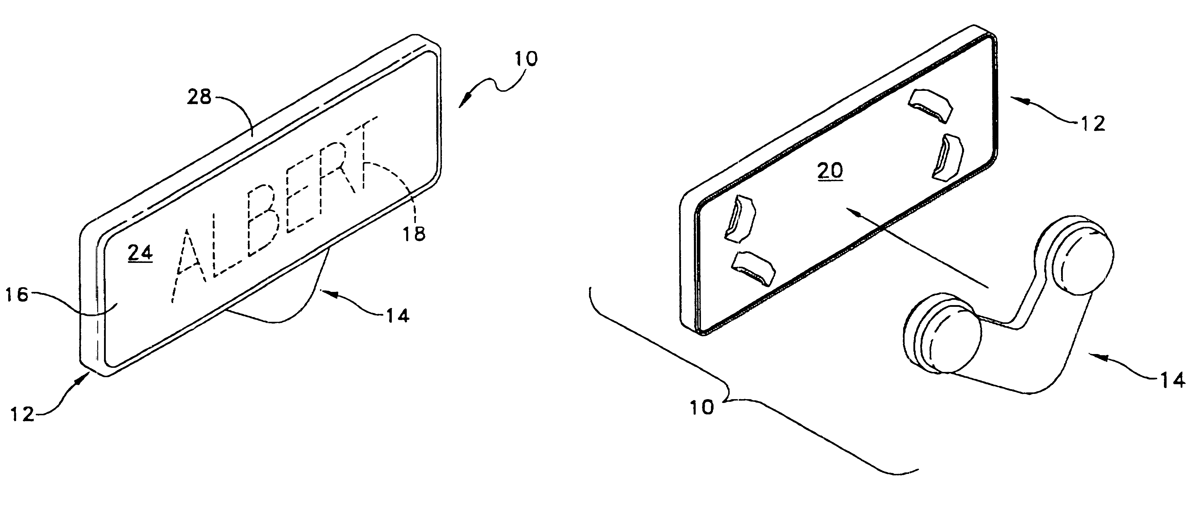
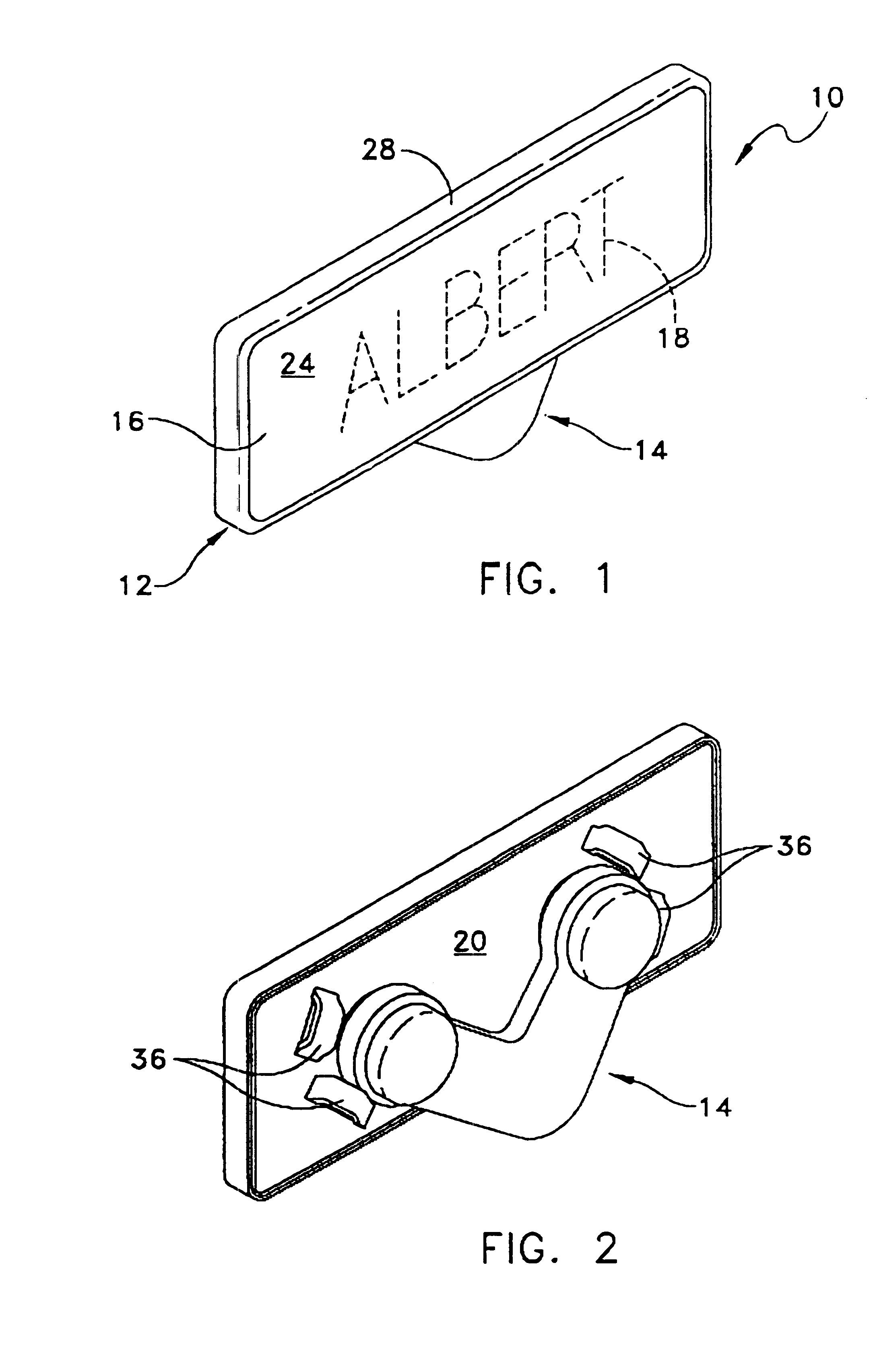
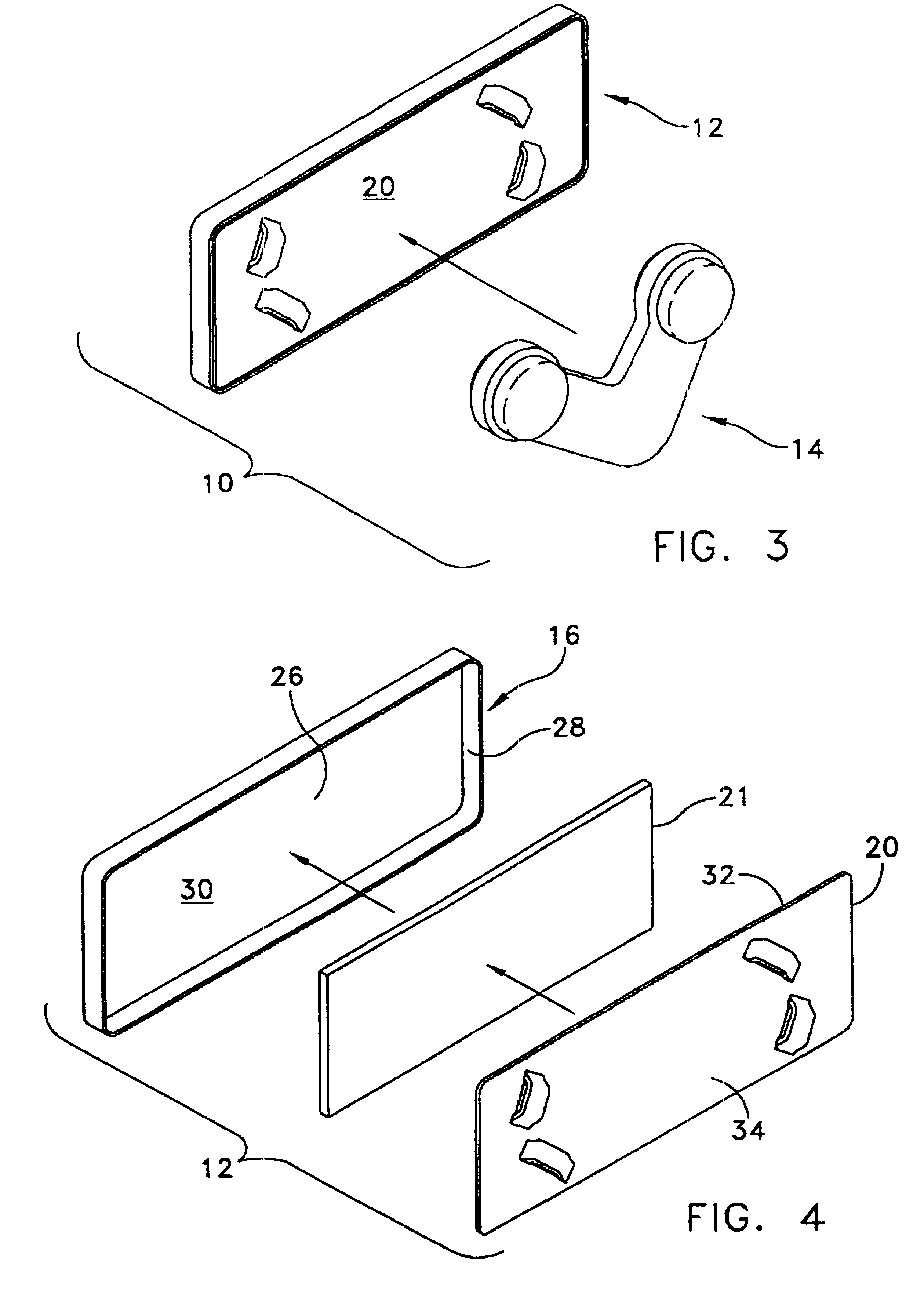
A magnetic name plate assembly 10 for attachment to an article of clothing according to the present invention is illustrated in FIGS. 1-9. The name plate assembly 10 preferably includes a name plate 12 and a connector 14 which are magnetically attracted to each other, and which are disposed on opposite sides of a piece of clothing during use such that the clothing is sandwiched therebetween.
The name plate preferably includes a face plate 16 for displaying indicia, such as a user's name 18, and a back plate 20 which is adapted to engage the article of clothing 22 (FIG. 8). The face plate 16 may be attached to the back plate 20 by adhesive, for example a strip of double sided adhesive tape 21. In the present embodiment, the face plate preferably includes a front surface 24 and a rear surface 26, with a lip 28 extending from the front surface and around a perimeter of the face plate. The lip defines a recess 30 for receiving the adhesive tape 21 and back plate 20 therein (FIG. 4). The ...
third embodiment
Referring now to FIGS. 12-13, the name plate assembly is illustrated. In this embodiment, all parts which are the same, or similar to, corresponding parts of the previous embodiments are noted with the same two last numbers, but preceded by the numeral "2". Name plate assembly 210 includes a name plate 212 and a connector 214 which are magnetically attracted to each other. In this embodiment, the name plate 212 is substantially identical to the name plate described with respect to FIGS. 1-9. The connector 214 has been modified, such that connector 214 preferably has a generally semi-circular shaped body, with a first portion 242 of the semi-circle extending beyond an edge 246 of the name plate 212. In the present embodiment, the semi-circular body has a generally solid, or continuous outer surface 243. Alternately, the outer surface may be non-continuous as shown in FIGS. 14-17. The first portion 242 is also sized to be gripped by the fingers of a user so that the user may grasp the...
fifth embodiment
Referring now to FIGS. 18-21, the name plate assembly is illustrated. In this embodiment, all parts which are the same, or similar to, corresponding parts of the previous embodiments are noted with the same two last numbers, but preceded by the numeral "4". Name plate assembly 410 includes a name plate 412 and a connector 414 which are magnetically attracted to each other. Name plate 412 may be constructed as described above with respect to FIGS. 1-9. However, the name plate 412 preferably includes an enclosure 437 (FIG. 20) in place of protrusions, in order to guide and limit movement of the name plate assembly and connector 414 relative to each other. In the present embodiment, the enclosure 437 is generally oval and includes a raised wall 445 around the perimeter thereof. Alternately, the enclosure may have any shape and may be formed as a recess wherein the base 447 is recessed relative to the remaining portion of the back plate 420, as would be known to those of skill in the ar...
PUM
 Abstract
Description
Claims
Application Information
 - R&D
- Intellectual Property
- Life Sciences
- Materials
- Tech Scout
- Unparalleled Data Quality
- Higher Quality Content
- 60% Fewer Hallucinations
Browse by: Latest US Patents, China's latest patents, Technical Efficacy Thesaurus, Application Domain, Technology Topic, Popular Technical Reports.
© 2025 PatSnap. All rights reserved.Legal|Privacy policy|Modern Slavery Act Transparency Statement|Sitemap|About US| Contact US: help@patsnap.com


