
Printer and printing method capable of double-sided printing

a printing method and printing method technology, applied in the direction of printing machines, recording equipment, instruments, etc., can solve the problems of inconsistency between the original image and the front and rear surfaces, the printing direction is likely to be error-prone, and the time waste is considerable long

Inactive Publication Date: 2004-01-06
FUJIFILM CORP +1
View PDF4 Cites 35 Cited by
  • Summary
  • Abstract
  • Description
  • Claims
  • Application Information

AI Technical Summary

Problems solved by technology

As an instruction of the feeding direction is not indicated, an error is likely to occur in a printing direction between the front and rear surfaces according to an error in the feeding direction of the recording sheet.
Also, if there is an error in the sequence of feeding of the recording sheets, inconsistency occurs in the original images between the front and rear surfaces.
Problems arise in that waste time is considerably long and that processing cannot be quick specifically when the feeding direction of a stack of the recording sheets in a great number is wrong, or when a sequence of supply of the recording sheets is wrong.

Method used


Image

  • Printer and printing method capable of double-sided printing
  • Printer and printing method capable of double-sided printing
  • Printer and printing method capable of double-sided printing

Examples


Embodiment Construction

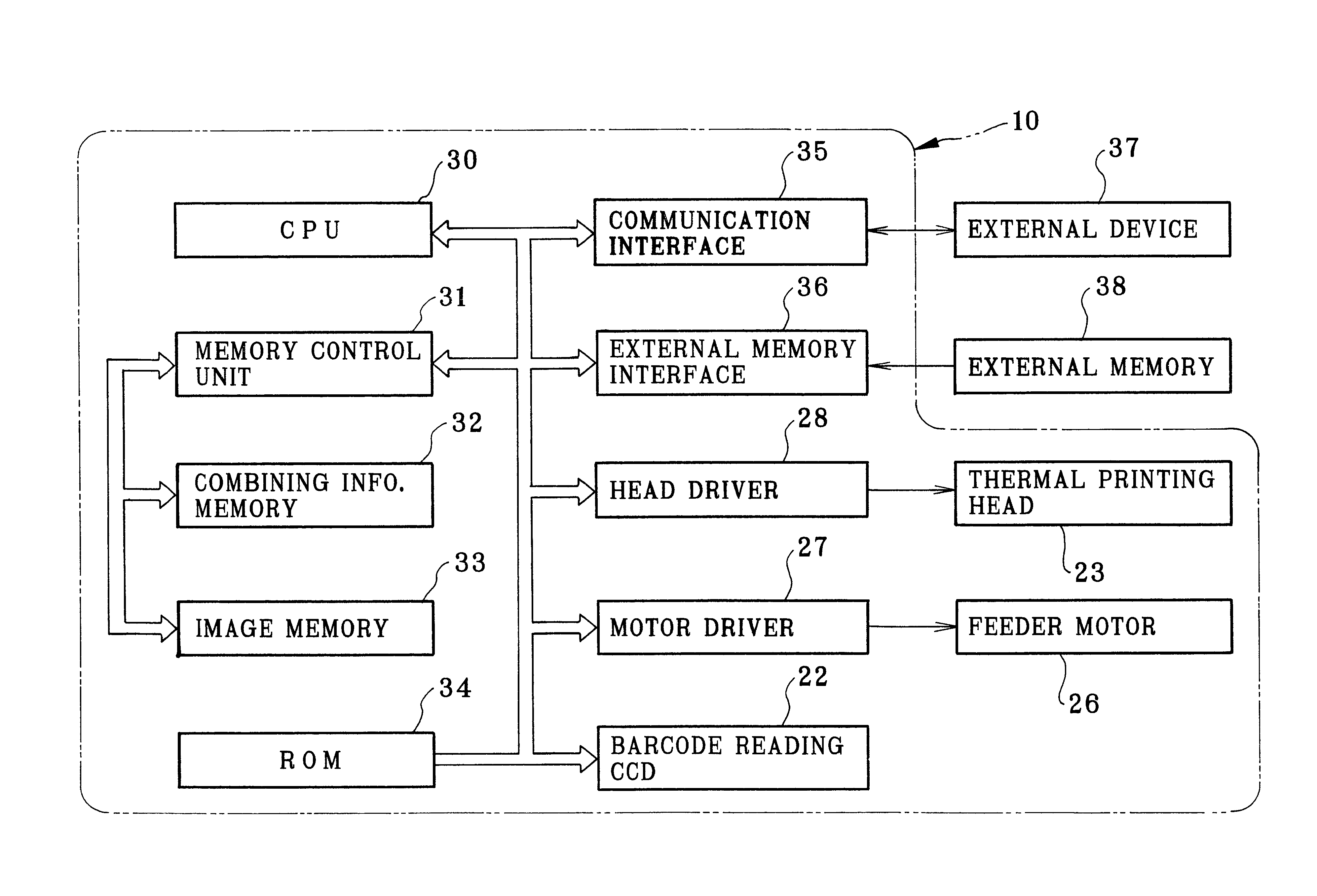
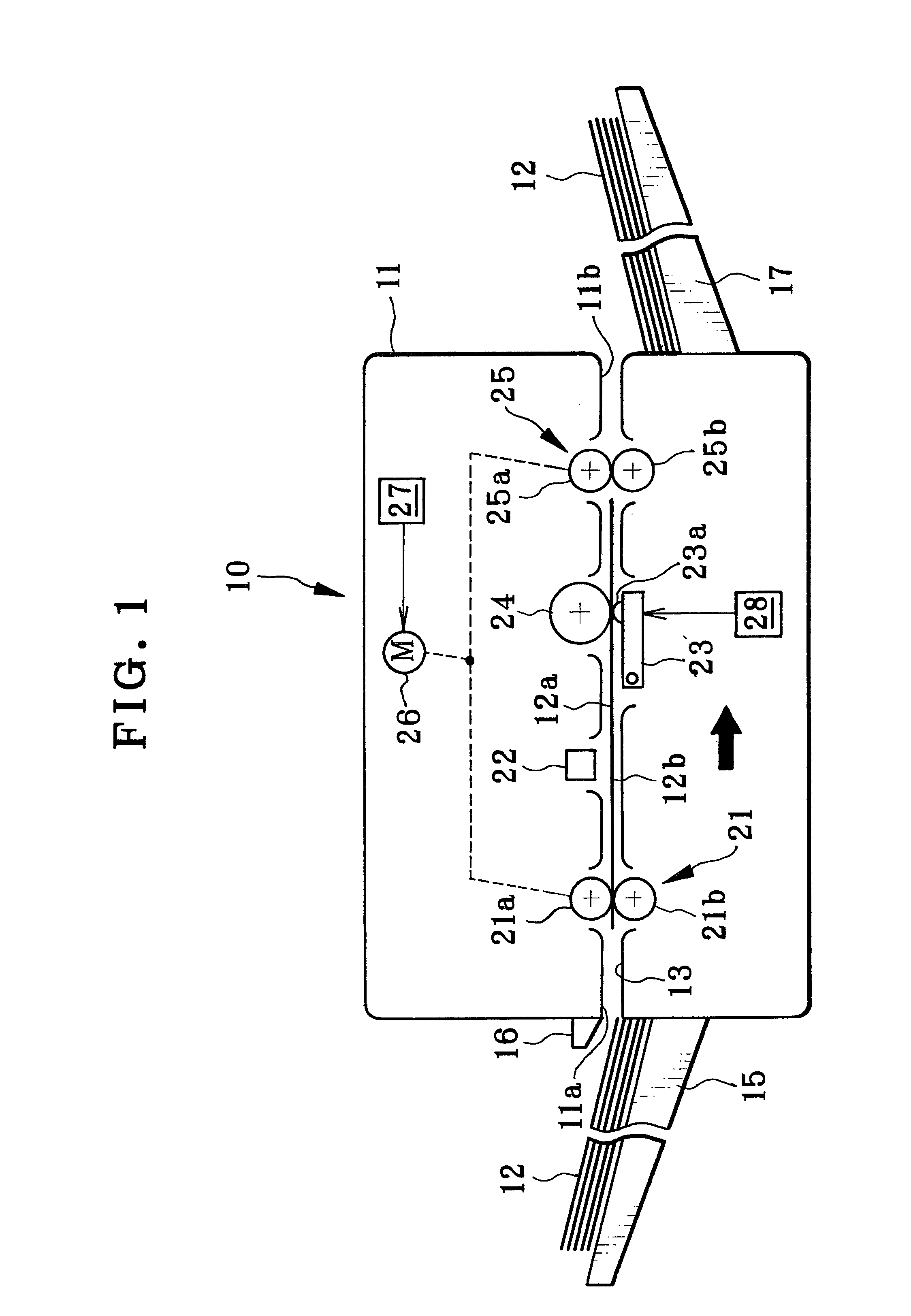
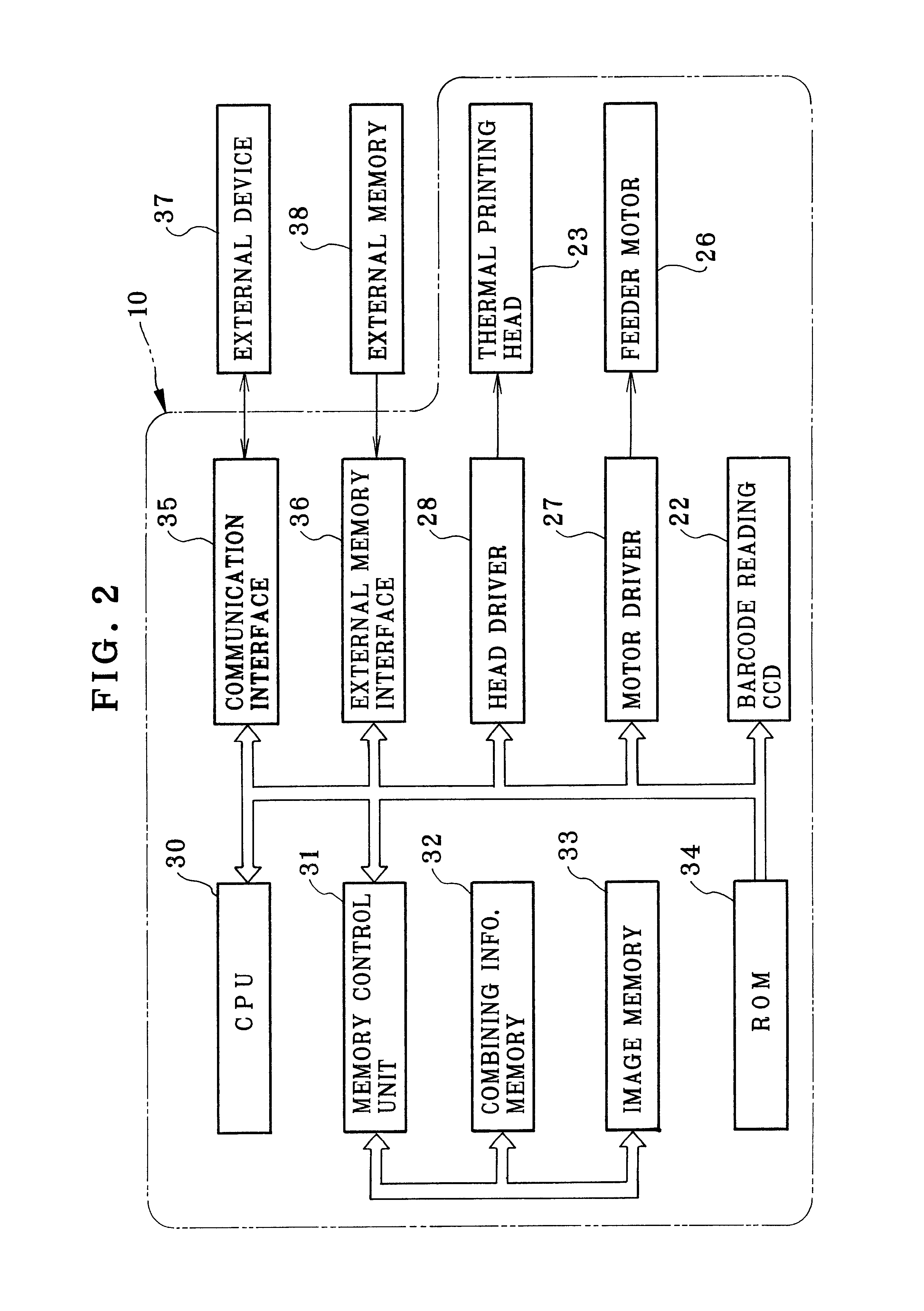
In FIGS. 1 and 2, a thermal printer 10 as image forming device of the present invention is illustrated. A printer body 11 of the thermal printer 10 has a feeding path 13 through which thermosensitive recording sheets 12 are fed in the arrow direction in the drawing. There are a sheet supply slot 11a and a sheet exit slot 11b formed in the printer body 11. The sheet supply slot 11a receives insertion of the recording sheets 12 into the feeding path 13. The sheet exit slot 11b ejects the recording sheets 12 from the feeding path 13. A sheet supply tray 15 is disposed at the sheet supply slot 11a for supporting the recording sheets 12 to be inserted. A cover ridge 16 protrudes from an upper side of the sheet supply slot 11a. A positioning target pointer 16a is indicated on the cover ridge 16. See FIG. 4. A sheet exit tray 17 is disposed at the sheet exit slot 11b for supporting the recording sheets 12 after being exited.

In the feeding path 13 are disposed feeder rollers 21, a bar code ...


PUM


Abstract

A thermal printer includes a thermal printing head in an image forming section, which prints an image on one of first and second surfaces of a recording sheet oriented downwards. Feeder rollers feed the recording sheet to the image forming section after the recording sheet is set in a sheet supply slot. The printer includes at least one first memory for storing first image data of an image for being printed on the first surface, and second image data of an image for being printed on the second surface. The first or second image data are read from the first memory, and input to the image forming section. A second memory stores information of discrimination bar code adapted for designating the second image data associated with the first image data according to common assignment to the recording sheet. The information of the discrimination bar code is read from the second memory at a time of printing with the first image data to the first surface, and is printed on the first surface by the image forming section. A reading CCD reads the discrimination bar code from the first surface at a time of printing to the second surface. The second image data is specified according to the discrimination bar code, read from the first memory, and input to the image forming section.

Description

1. Field of the InventionThe present invention relates to a printer and printing method capable of double-sided printing. More particularly, the present invention relates to a printer and printing method in which images are printed to two surfaces of a recording sheet after loading of the recording sheet for two times, and a combination of the images can be correct in a print without an error.2. Description Related to the Prior ArtA general type of a printer is normally operated to print an image to one recording surface at one time, but can be used for double-sided printing in which a first image is printed to one front surface of a recording sheet, and then a second image is printed to its rear surface after turning over the recording sheet. For reliability in the operation of the double-sided printing, it is important to set an orientation of the recording sheet for a recording head direction of the printer at the time of printing to the rear surface, and also to check an image t...

Claims


Application Information

Patent Timeline
Patent Type & Authority Patents(United States)
IPC IPC(8): B41J11/00B41J2/355B41J3/60B41J25/20B41J2/32B41J5/30B41J21/16B65H1/04
CPCB41J2/355B41J3/60B41J11/009
Inventor MIYAZAKI, TAKAO
Owner FUJIFILM CORP
Learn More