Male incontinence device

a technology for incontinence and sex, which is applied in the field of incontinence devices, can solve the problems of growing incontinence and achieve the effect of effective and comfortable wear

Inactive Publication Date: 2004-01-20
MARK MISKIE +1
View PDF26 Cites 26 Cited by
  • Summary
  • Abstract
  • Description
  • Claims
  • Application Information

AI Technical Summary

Benefits of technology

to provide a male incontinence device which is effective and comfortable to wear.
Referring to FIGS. 1, 5, and 6, the support harness 20 is worn around the upper thighs of the user, and includes first and second adjustable, elastic leg straps 42 and 44 and a pair of elastic receptacle support straps 46 and 48. The receptacle support straps 46, 48 interconnect the leg straps 42, 44 and define an opening sufficient to receive and frictionally secure the receptacle 12 to the harness 20. Preferably, the receptacle 12 includes spaced positioning ribs 51 and 52 for properly positioning and retaining the straps 46, 48 on the receptacle 12. A thin rubber inlay (not shown) may also be included on the inside of the straps 42, 44, 46, and 48 for increased holding strength. The harness 20 is worn on the user to locate the receptacle 12 in the operative position shown in FIG. 1. Each of the leg straps 42 and 44 preferably includes an adjustment frame 54 and 55 for allowing size adjustment of the leg openings to fit the particular user. As best shown in FIGS. 5 and 6, flex areas 56 and 58 are formed at respective ends of the receptacle straps 46 and 48 adjacent the receptacle opening in order to accommodate movement of the leg straps 42 and 44 without substantial corresponding movement of the receptacle straps 46, 48 and receptacle 12. The flex areas 56 and 58 are defined by respective pairs of spaced stitch lines 61, 62 and 63, 64 located on either side of the receptacle opening. FIG. 6 illustrates the flex area 56 in greater detail. Stitch line 61 extends through the two receptacle support straps 46 and 48 to form one end closure for the receptacle opening. Stitch line 62 extends through the receptacle strap 46 and leg strap 42. A corresponding stitch line (not shown) extends through the other receptacle strap 48 and leg strap 42 at point 65. The other flex area 58 is formed in an identical manner. The flex areas 56 and 58 cooperate during activity of the user to promote comfort and provide an increased freedom of movement.

Problems solved by technology

Incontinence is a growing problem, particularly in those adults ages 65 and older.

Method used


Image

  • Male incontinence device
  • Male incontinence device
  • Male incontinence device

Examples


Embodiment Construction

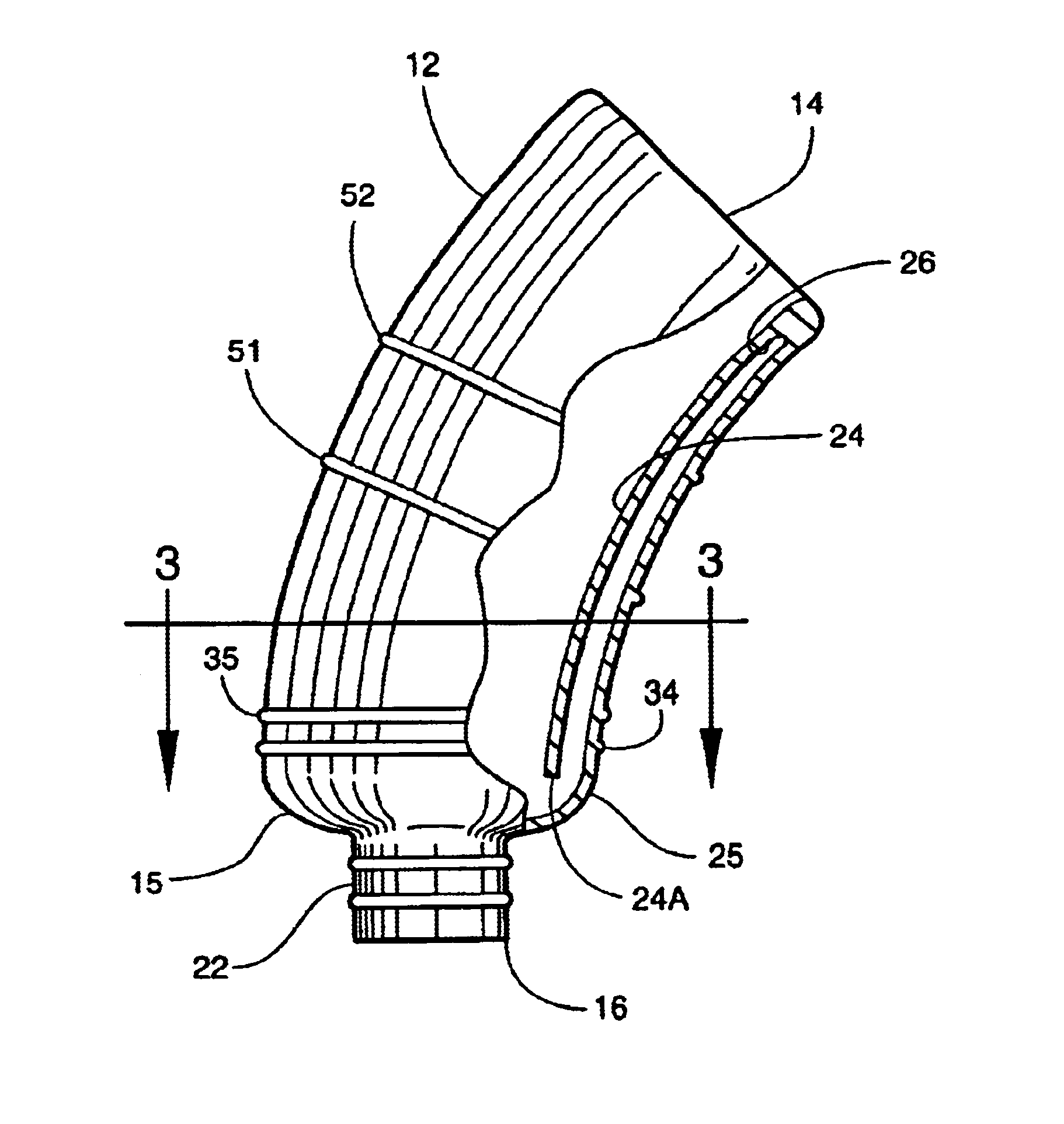
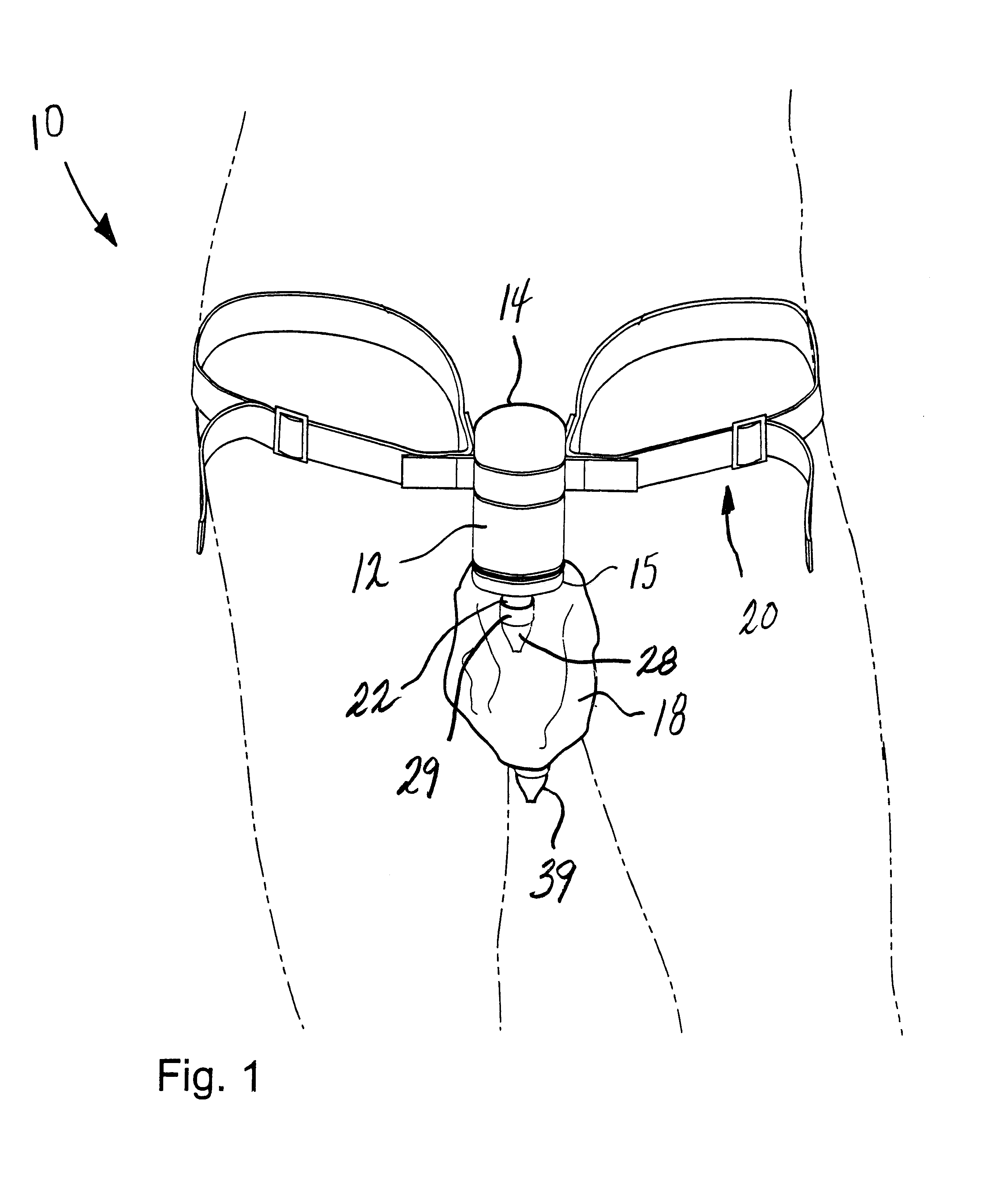
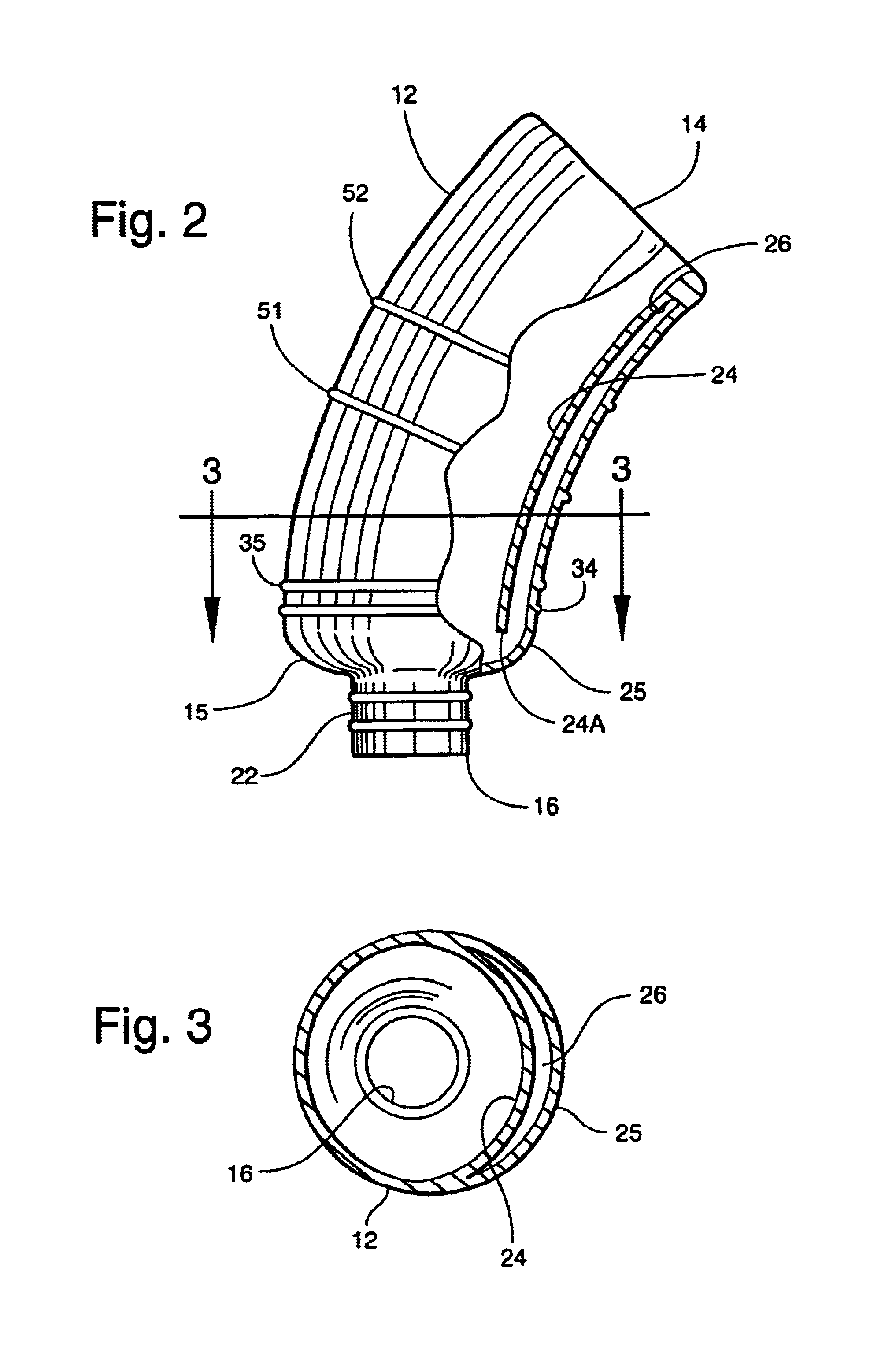
Referring now specifically to the drawings, a male incontinence device according to the present invention is illustrated in FIG. 1 and shown generally at reference numeral 10. The device 10 is intended for use by males suffering from moderate to severe incontinence. The device includes a hollow receptacle 12 having a first open end 14 adapted for receiving the penis of the user and a second end 15 defining a urine discharge port 16. A urine collection bag 18 is attached to the receptacle 12 over the discharge port 16 to collect urine discharged by the user during wear. A removable support harness 20 is worn around the upper thighs of the user, and is designed to support the receptacle 12 in an operative position over the penis. Each of the receptacle 12, urine collection bag 18, and support harness 20 is described in further detail below.

Referring to FIGS. 1, 2, and 3, the receptacle 12 is formed of a shape-retaining material, such as a thin rigid or semi-rigid molded plastic, which...


PUM


Abstract

A male incontinence device includes a receptacle formed of a shape-retaining material, and having a first open end adapted for receiving the penis of a user and a second end defining a urine discharge port. The discharge port is adapted for being located forward of the penis. A back flow chamber is formed with an interior of the receptacle, and is adapted for capturing urine flowing backward towards the user and away from the discharge port. A collection bag has a mouth communicating with the discharge port for collecting urine discharged through the receptacle. A support harness is adapted for being worn by the user to support the receptacle in an operative position during use.

Description

TECHNICAL FIELD AND BACKGROUND OF THE INVENTIONThis invention relates to a male incontinence device. The invention fits securely and comfortably on the user without adhesives, tape, glue, or other constricting elements which may irritate and injure the skin. The invention is relatively inconspicuous under clothing, and provides a freedom of movement often sacrificed with commercially available male incontinence devices and catheters. Users can wear the present invention with confidence and without a feeling of self-consciousness.Incontinence is a growing problem, particularly in those adults ages 65 and older. Approximately two million males in the United States suffer moderate to severe incontinence. Common causes for this condition include an enlarged prostate, prostate cancer, pelvic trauma, spinal cord injury, and medication side-effects. Over $16 billion is spent annually on incontinence related care.The present invention addresses the limitations of certain prior art devices a...

Claims


Application Information

Patent Timeline
Patent Type & Authority Patents(United States)
IPC IPC(8): A61F5/451A61F5/453
CPCA61F5/453
Inventor MISKIE, JOHN D.
Owner MARK MISKIE
Why Eureka
Try Eureka