
Protective garment with an inflatable floatation bladder

a technology of floatation bladder and protective garment, which is applied in the field of body armour, can solve the problems of high stress and/or danger, restricted free movement of clothing, and high risk to wearers, and achieves the effects of reliable, smooth and automated enlargement of the internal volume, increased movement within the vest, and increased stress and/or danger

Active Publication Date: 2015-12-03
BCB INT
View PDF0 Cites 11 Cited by
  • Summary
  • Abstract
  • Description
  • Claims
  • Application Information

AI Technical Summary

Benefits of technology

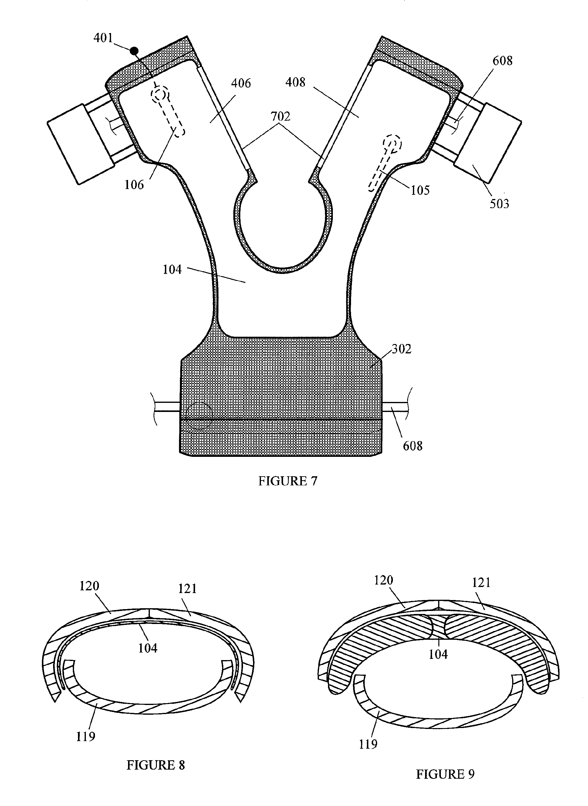
The waist and / or waistband release mechanism ensures the protective vest can automatically enlarge at the point of inflation, without the need for manual adjustment in high stress or danger situations. Additionally, the invention provides a load-bearing connection at each shoulder of the protective vest that automatically breaks when the inflation bladder inflates, releasing excess material and enlarging the size of the protective vest. This allows the vest to better accommodate the inflated bladder and provide improved movement within it.

Problems solved by technology

In building up the layers, the resultant garment tends to be very stiff and restrictive of free movement.
Clearly, greater protection is achieved through the use of large plates of hard armour, although this has a drawback in that the plates are both relatively heavy and cumbersome and thus may become a risk to the wearer when submerged in water.
Regardless, the additional loading makes swimming difficult and the bulk of the inflatable jacket generally restrictive and uncomfortable.
Unfortunately, increasing the inflated volume of the bladder further restricts movement in existing designs, especially around the upper arms and neck region of the protective vest where bladder inflation is less constrained and the bladder (even if shaped) has a tendency to expand into any open space.
Additionally, higher pressures within the bladder also generally restrict movement and these higher pressures must be overcome to facilitate arm and neck movement.
Restricted movement, and resultant increased discomfort, are undesirable at times when a bladder is deployed within the constricting environment of a protective vest, particularly since the wearer will invariably be under considerable physical duress and / or stress in a hostile environment in which munitions are being targeted towards their general vicinity.
Given that a soldier, for example, might be a target who is being shot at directly, jettisoning the protective vest once the bladder is inflated is therefore not a realistic option, since body protection of the wearer would be entirely compromised.
Conversely, having an over-sized protective vest that can always accommodate an inflated bladder is also not viable since the protective vest either (a) would not fit in which case the additional bagginess in the protective vest would likely impair movement or present a snagging risk, and / or (b) the over-sized nature of the protective vest would allow the relative position of the armour relative to the wearer's organs to change and thereby compromise the effectiveness of the armour.
Designing a protective vest that is too big is therefore also not considered a sensible option since the bladder is, for the most part, always stored in a deflated state.

Method used


Image

  • Protective garment with an inflatable floatation bladder
  • Protective garment with an inflatable floatation bladder
  • Protective garment with an inflatable floatation bladder

Examples


Embodiment Construction

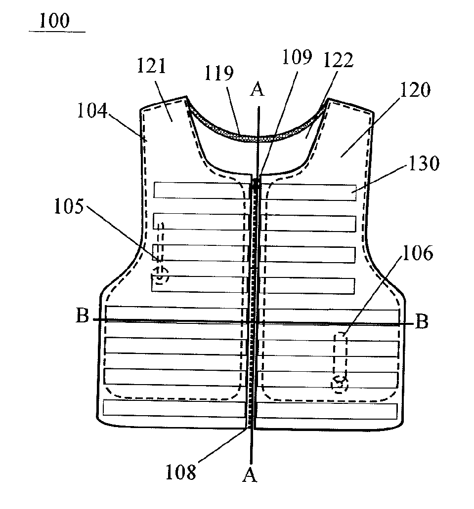
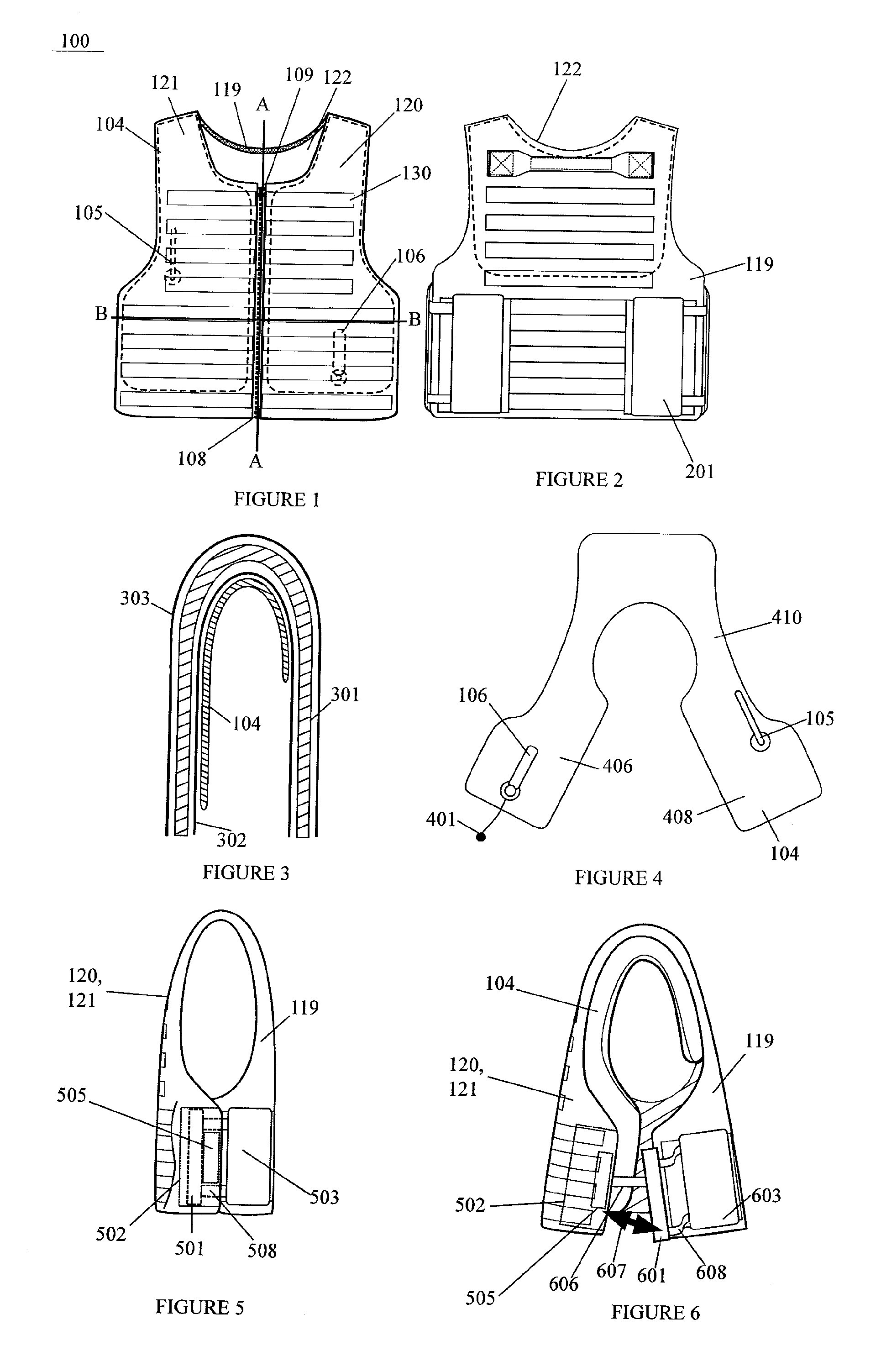
[0037]In FIG. 1, an armour vest 100 is configured to cover the torso of a user to protect generally at least some of the five vital organs, namely the heart, lungs, kidneys, liver and pancreas. The armour may cover other areas, as desired.

[0038]The vest may have a low profile to enable it to be worn under suitable outer clothing and thus as a concealed garment.

[0039]The armour vest 100 includes a detachable floatation bladder 104 providing, when deployed and inflated, buoyancy to the armour vest 100 and its wearer. The armour vest, in terms of its general construction, includes front left and right portions 120, 121 that attach to a back portion 119 at the shoulders, with a front opening 108 running from a neck opening to the bottom of the armour vest closed conventionally by a zipper 109. The front portions 120, 121 in combination with back portion 119 define a conventional sleeveless vest, with the front and back portions suitably sculpted. To provide an envelope and complete the ...


PUM


Abstract

An armour vest includes front and rear portions that realize or otherwise mount armour plate or soft armour pads over a wearer's vital organs. A floatation bladder is stored and deployed under the protection of the armour. The armour vest is expandable to accommodate and at least partially protect the floatation bladder when it is inflated. In either a single or multi-stage process, the armour vest's volume is increased by automatically releasing buckles that increase separation between the front and rear portions around the waist and, in an embodiment, also at the shoulders of the armour vest. In a deflated state, shoulder connectors provide a load-bearing connection between the front and rear portions of the armour vest. Inflation of the bladder, either manually actuated by pulling a webbing trigger handle or automatically with immersion, causes a different load-bearing shoulder bridge to be brought into operation at the shoulders of the amour vest. The shoulder bridge is realized by the taking up of folds of fabric, which folds are released with the breaking of the buckle connection. Increased comfort and manoeuvrability are therefore afforded to the wearer of the vest.

Description

CROSS-REFERENCE TO RELATED APPLICATIONS[0001]This application claims priority to and the benefit of Great Britain Patent Application No. 1500455.9, entitled “Protective Garment with an Inflatable Floatation Bladder”, filed on Jan. 12, 2015, and Great Britain Patent Application No. 1409842.0, entitled “Protective Garment with an Inflatable Floatation Bladder”, filed on Jun. 3, 2014. All of the aforementioned applications are incorporated by reference herein in their entirety.FIELD OF THE INVENTION[0002]This invention relates, in general, to body armour that provides a protective shield against general bodily injury or acute trauma. More particularly, but not exclusively, the present invention relates to personal body armour that can provide ballistic protection against projectile threats, such as high velocity rifle rounds, and which personal body armour is used in conjunction with an inflatable floatation bladder that is deployed in water to prevent sinkingSUMMARY OF THE PRIOR ART[0...

Claims


Application Information

Patent Timeline
Patent Type & Authority Applications(United States)
IPC IPC(8): F41H1/02A41D1/04
CPCF41H1/02A41D2600/00A41D1/04
Inventor SEARLE, MATTHEWLEWIS, CHRISTOPHER MARK
Owner BCB INT
Learn More