
Centrifugal force pendulum device

a centrifugal force and pendulum technology, applied in the direction of flywheels, springs/dampers, rotating vibration suppression, etc., can solve the problems of unsatisfactory noise, vibration, failure of components, etc., to improve the improve the reliability improve the effect of extinguishing effect of centrifugal force oscillating devices

Inactive Publication Date: 2013-10-31
SCHAEFFLER TECH AG & CO KG
View PDF19 Cites 11 Cited by
  • Summary
  • Abstract
  • Description
  • Claims
  • Application Information

AI Technical Summary

Benefits of technology

The invention proposes a centrifugal force oscillating device with improved extinguishing effect and increased reliability. The device has oscillating masses that can move to a limited extent radially and / or circumferentially relative to each other, which allows for additional freedom of movement and better extinguishing of the oscillating force. The device also eliminates the need for fastening elements and cut-outs, which increases the maximum pivoting angle of the oscillating masses and reduces space requirement.

Problems solved by technology

The torsional vibrations can arise through the operation of a combustion engine and lead to unpleasant noises, vibrations, but also to failure of components.

Method used


Image

  • Centrifugal force pendulum device
  • Centrifugal force pendulum device
  • Centrifugal force pendulum device

Examples


Embodiment Construction

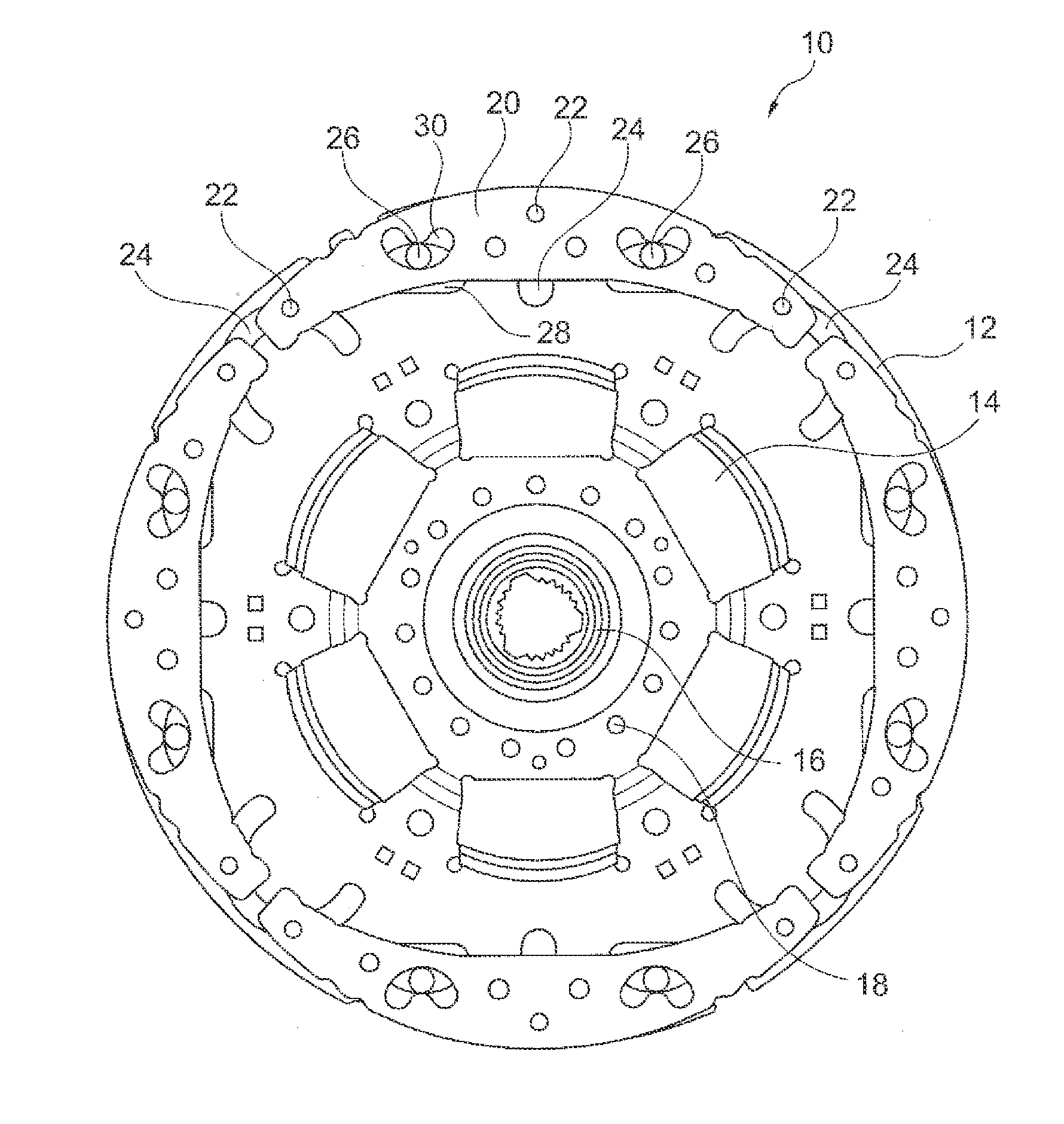
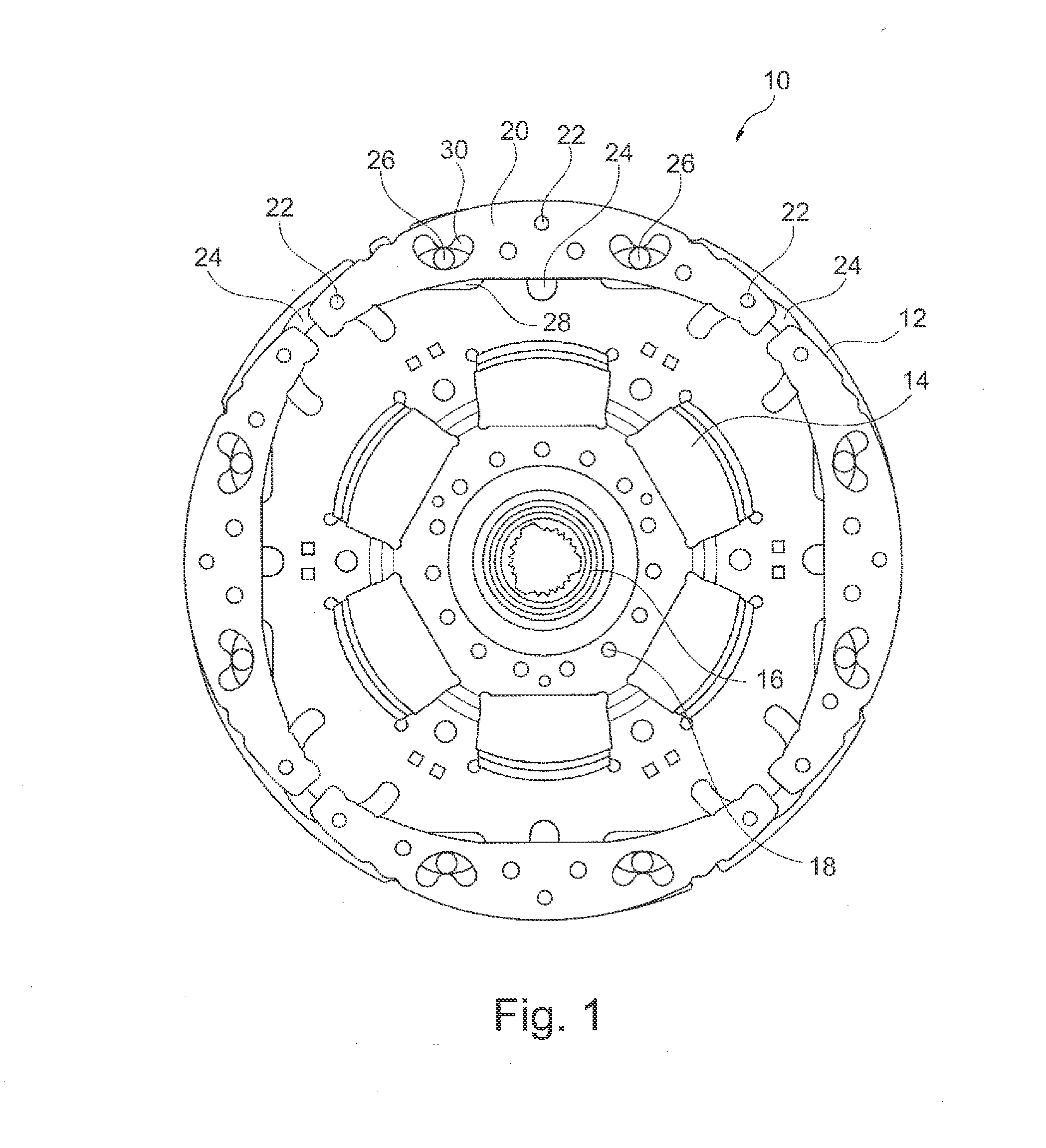
[0020]FIG. 1 shows a side view of a centrifugal force oscillating device 10 according to the state of the art. The centrifugal force oscillating device 10 comprises an oscillating mass carrier 12 rotatable around an axis of rotation, which is formed here as a component of a torsional vibration damper that acts to damp torsional vibrations. To that end, spring windows 14 are formed in the oscillating mass carrier to receive energy storage elements, for example coil springs. The energy storage elements are operatively connected to the oscillating mass carrier 12 and a damper component (not shown here) of the torsional vibration damper, to make it possible to rotate the damper component relative to the oscillating mass carrier 12 through the effect of the energy storage elements, to which end the latter may be brought into engagement with the damper component and the oscillating mass carrier.

[0021]Radially within the spring window 14 an output hub 16 is attached to the oscillating mass...


PUM


Abstract

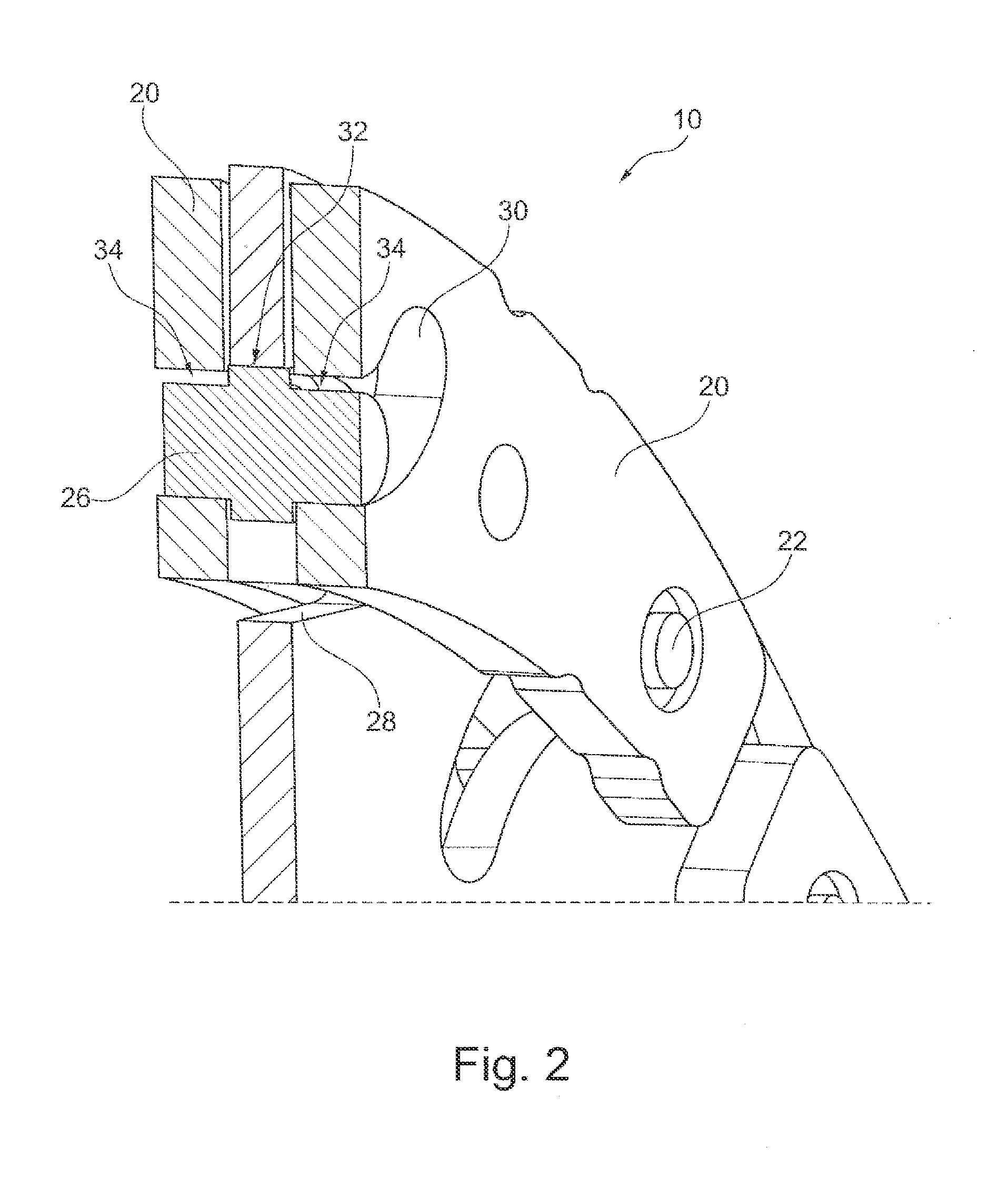
A centrifugal force oscillating device having oscillating masses that are situated axially on both sides of an oscillating mass carrier rotatable around an axis of rotation and form an oscillating mass pair, where the oscillating masses can be swiveled to a limited extent along an oscillation path opposite the oscillating mass carrier with the help of at least one roll-off element that can be rolled off in cut-outs in both the oscillating mass carrier and the oscillating masses, and where the oscillating masses can be moved to a limited extent axially relative to each other to form the oscillating mass pair, and where the oscillating masses of an oscillating mass pair are movable to a limited extent radially and / or circumferentially relative to each other.

Description

CROSS-REFERENCE TO RELATED APPLICATIONS[0001]This application is filed under 35 U.S.C. §120 and §365(c) as a continuation of International Patent Application PCT / DE2011 / 002098, filed Dec. 9, 2011, which application claims priority from German Patent Application No. DE 10 2010 056 163.0, filed Dec. 24, 2010, which applications are incorporated herein by reference in their entireties.FIELD OF THE INVENTION[0002]The invention relates to a centrifugal force oscillating device.BACKGROUND OF THE INVENTION[0003]A centrifugal force oscillating device for damping and / or extinguishing torsional vibrations in a drive train of a motor vehicle is known from DE 10 2006 028 556 A1. The torsional vibrations can arise through the operation of a combustion engine and lead to unpleasant noises, vibrations, but also to failure of components. The centrifugal force oscillating device has oscillating masses that are situated axially on both sides of an oscillating mass carrier rotatable around an axis of ...

Claims


Application Information

Patent Timeline
IPC IPC(8): F16F15/30
CPCF16F15/30F16F15/145Y10T74/2128
Inventor BARAL, FLORIANSCHNAEDELBACH, DAVID
Owner SCHAEFFLER TECH AG & CO KG
Learn More