
Oxygen-enriched and flameless gas burner and control method thereof

A gas burner and burner technology, which is applied in the combustion method, gas fuel burner, burner and other directions, can solve the problem of poor uniformity of furnace temperature distribution, oxidative burning loss of steel billet and increase of slag amount, and thermal NOx. Formation increase and other problems, to achieve the effect of reducing NOx formation, improving ignition, and reducing waste heat loss of flue gas

Active Publication Date: 2015-01-07
WISDRI WUHAN WIS IND FURNACE
View PDF12 Cites 16 Cited by
  • Summary
  • Abstract
  • Description
  • Claims
  • Application Information

AI Technical Summary

Problems solved by technology

For traditional heating furnace burners, if direct air is mixed with oxygen to achieve oxygen-enriched combustion, the combustion rate will be accelerated, the flame will be shortened, and the combustion area will be more concentrated. The thermal system runs in the opposite direction and is counterproductive, which makes the uniformity of the furnace temperature distribution worse, the formation of thermal NOx increases sharply, and at the same time the oxidation burning loss of the billet and the amount of slag will increase, which is not conducive to improving the quality of steel production
For the so-called oxygen-spray gun-type oxygen-enrichment method, in the field of heating furnaces, it basically solves the problem of insufficient heating capacity or increases production capacity, and does not really solve the process system, furnace temperature uniformity, pollution generation, and oxidation burning caused by oxygen-enrichment. question

Method used


Image

  • Oxygen-enriched and flameless gas burner and control method thereof
  • Oxygen-enriched and flameless gas burner and control method thereof
  • Oxygen-enriched and flameless gas burner and control method thereof

Examples


Embodiment Construction

[0034] It should be understood that the specific embodiments described here are only used to explain the present invention, not to limit the present invention.

[0035] It should be noted that, in the description of the present invention, the terms "horizontal", "vertical", "upper", "lower", "front", "rear", "left", "right", "vertical", The orientation or positional relationship indicated by "horizontal", "top", "bottom", "inner", "outer", etc. is based on the orientation or positional relationship shown in the drawings, and is only for the convenience of describing the present invention and simplifying the description, and It is not to indicate or imply that the device or element referred to must have a particular orientation, be constructed in a particular orientation, or operate in a particular orientation, and thus should not be construed as limiting the invention.

[0036] The invention provides an oxygen-enriched flameless gas burner.

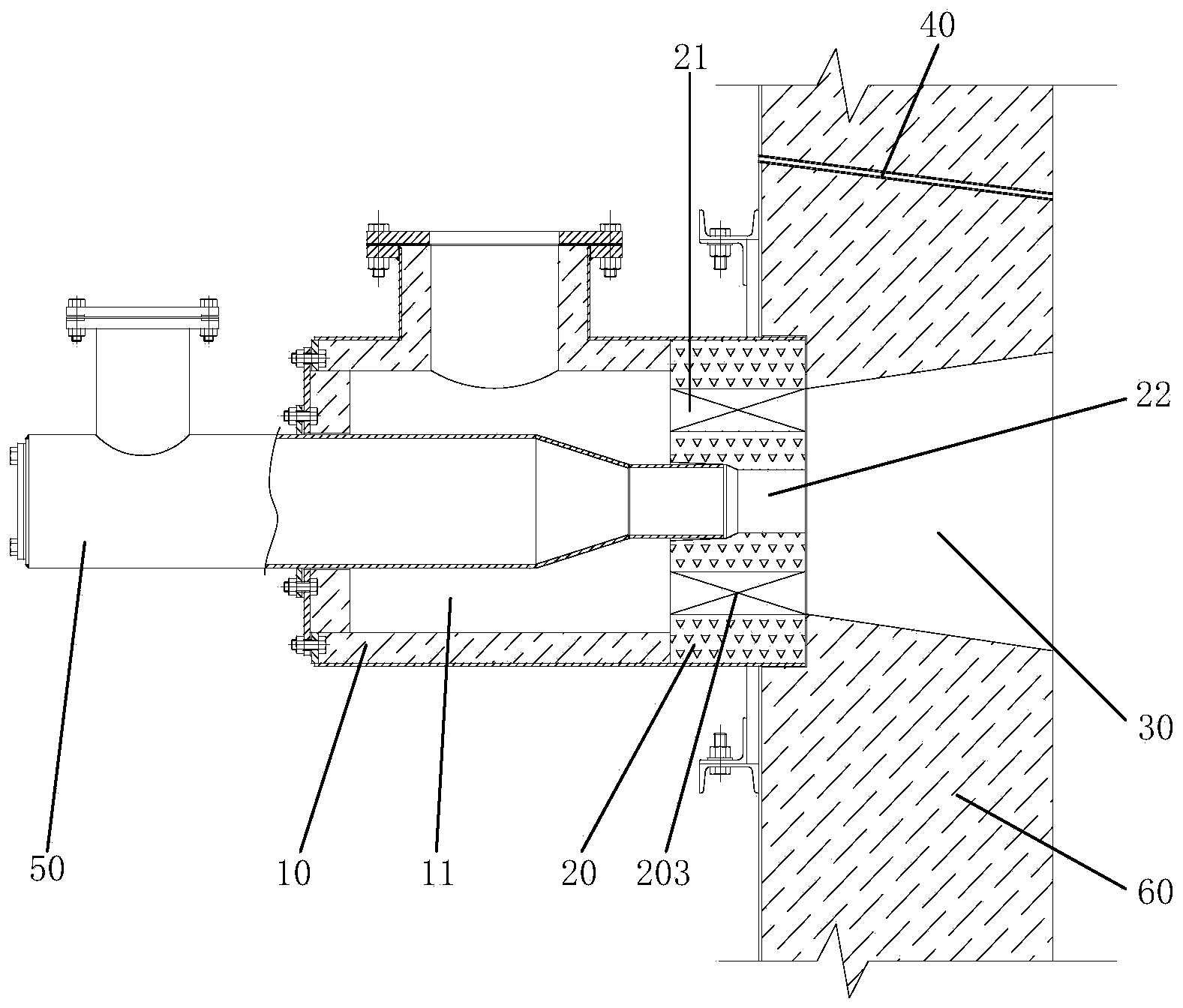
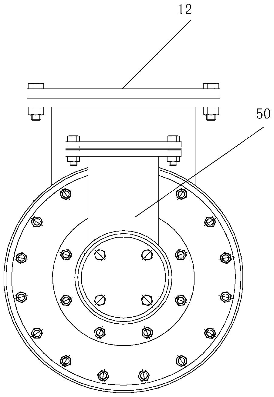
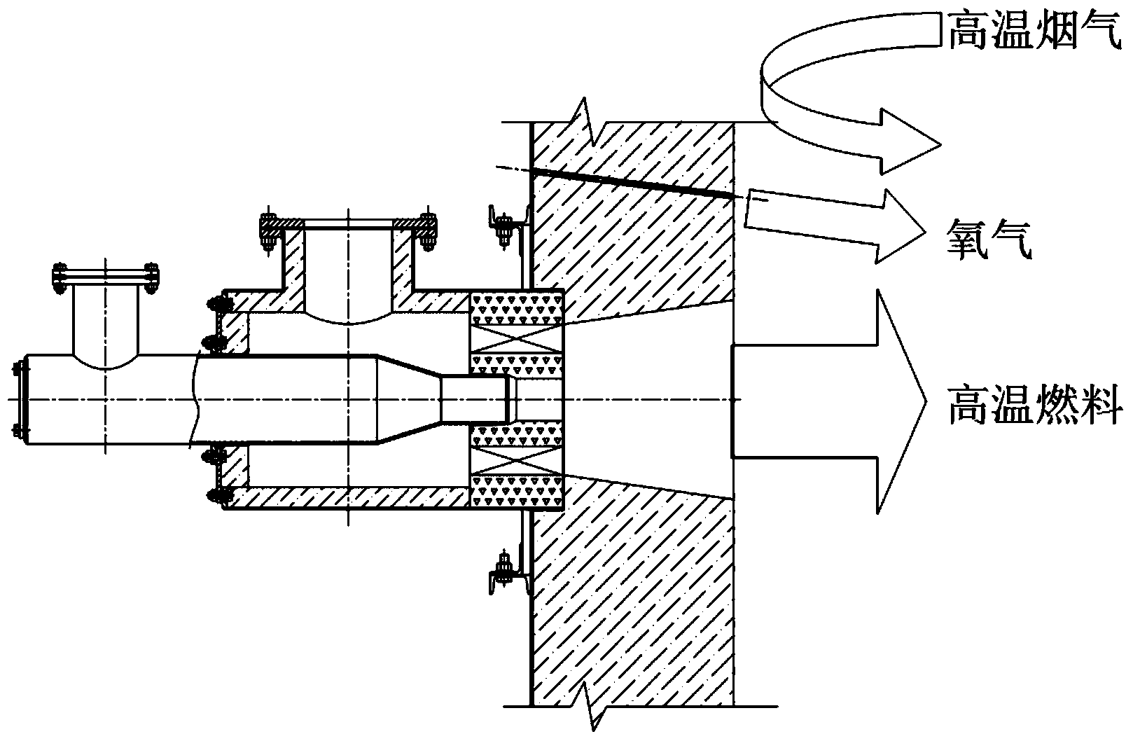
[0037] refer to figure 1 and f...


PUM


Abstract

The invention discloses an oxygen-enriched and flameless gas burner which comprises a burner casing, an air distribution plate, a prechamber, an oxygen nozzle and a fuel nozzle. A channel penetrating a wall body of a furnace wall of a heating furnace is arranged on the furnace wall. The burner casing is installed on one side of the channel, and the prechamber is formed in the space in the channel. A combustion-supporting air channel is arranged on the burner casing, and the fuel nozzle penetrates through the burner casing in an inserting mode. A fuel channel is arranged on the fuel nozzle. An air inlet and a fuel inlet are arranged on the air distribution plate. The oxygen nozzle is provided with an oxygen pipe and installed on the furnace wall of the heating furnace, the oxygen channel is communicated with a hearth of the heating furnace, the oxygen nozzle is slantingly arranged on the furnace wall of the heating furnace, and a spray head end of the oxygen nozzle is close to the prechamber. The oxygen-enriched and flameless gas burner organically combines the dilution combustion technology and the oxygen-enriched combustion technolog, achieves flameless combustion in the furnace, meanwhile optimizing temperature distribution in the furnace, and reduces NOx emission.

Description

technical field [0001] The invention relates to the field of gas fuel combustion equipment and methods, in particular to an oxygen-enriched flameless gas burner and a control method thereof. Background technique [0002] The iron and steel industry is not only a major energy consumer, but also a major pollutant emitter. Improving the resource utilization rate in the iron and steel production process will reduce the production cost of iron and steel enterprises on the one hand, and on the other hand is of great significance to reducing pollutant emissions. [0003] At present, facing the increase of environmental protection emission assessment and the intensification of market price competition, the realization of oxygen-enriched combustion by increasing the oxygen concentration in the air has become a popular new combustion method. Oxygen-enriched combustion has the advantages of increasing the combustion temperature of the furnace, reducing the waste heat loss of flue gas, ...

Claims


Application Information

Patent Timeline
Patent Type & Authority Applications(China)
IPC IPC(8): F23D14/24F23D14/46
CPCF23D14/24F23D14/46Y02E20/34
Inventor 李卫杰刘豪周末段殿勇涂垚杰
Owner WISDRI WUHAN WIS IND FURNACE
Learn More