Oxide magnetic material and sintered magnet

A technology of magnetic materials and sintered magnets, which is applied in the fields of magnetism of inorganic materials, manufacturing of inductors/transformers/magnets, electrical components, etc., and can solve problems such as inability to meet high coercive force and high squareness ratio, inability to apply motors, and poor squareness ratio

Active Publication Date: 2007-05-02
HITACHI METALS LTD
View PDF3 Cites 16 Cited by
  • Summary
  • Abstract
  • Description
  • Claims
  • Application Information

AI Technical Summary

Problems solved by technology

[0017] Thus, for the CaLaCo ferrite in Patent Document 3, the anisotropic magnetic field H A It has characteristics exceeding SrLaCo ferrite, and Br and HcJ have characteristics comparable to SrLaCo ferrite, but the squareness ratio is very poor, and it cannot satisfy both high coercive force and high squareness ratio, and cannot be used for various applications such as motors

Method used


Image

  • Oxide magnetic material and sintered magnet
  • Oxide magnetic material and sintered magnet
  • Oxide magnetic material and sintered magnet

Examples


Embodiment 1

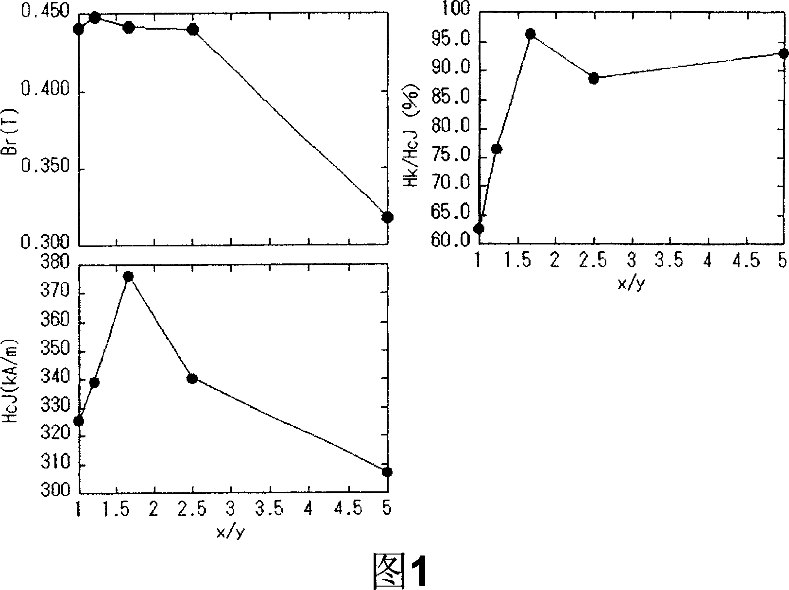
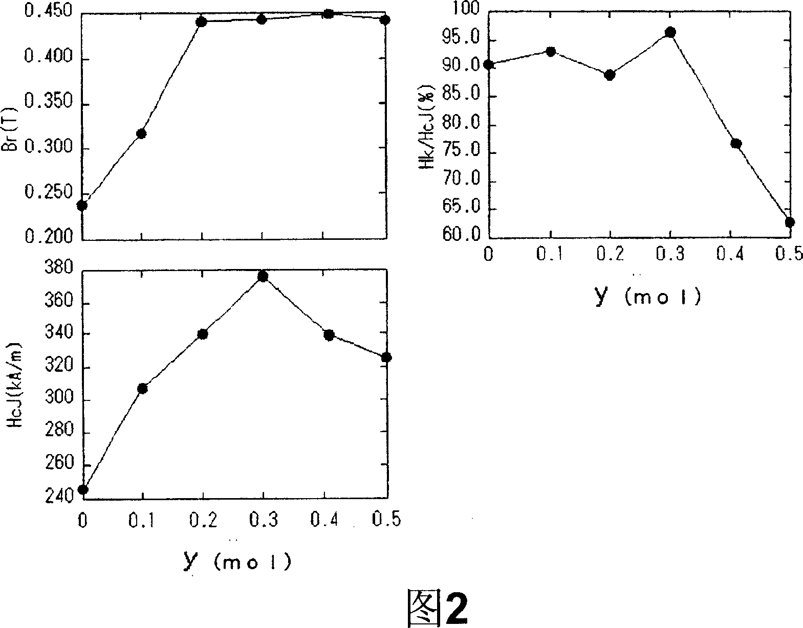
[0094] Prepare CaCO 3 Powder, La 2 o 3 Powder, Fe 2 o 3 Powder (particle size 0.6μm) and Co 3 o 4 And with each powder, so that in formula (1-x)CaO·(x / 2)La 2 o 3 ·(n-y / 2)Fe 2 o 3 · In yCoO, x=0.5, 1≤x / y, 0≤y≤0.5, n=5.4. The obtained raw material powders were mixed in a wet ball mill for 4 hours, dried and sized. Next, it fired at 1300 degreeC for 3 hours in air|atmosphere, and obtained the powdery fired body.

[0095] Next, 0.6% by mass of CaCO in terms of CaO was added to the calcined body. 3 Powder, 0.45% by mass SiO 2 The powder is finely pulverized in a wet ball mill using water as a solvent until the average particle size of the air permeation method reaches 0.55 μm. The solvent in the obtained finely pulverized slurry was removed, and pressure molding was performed in a magnetic field. Press molding was performed so that the pressing direction of the press was parallel to the direction of the magnetic field, and the magnetic field strength was 13 kOe. The ...

Embodiment 2

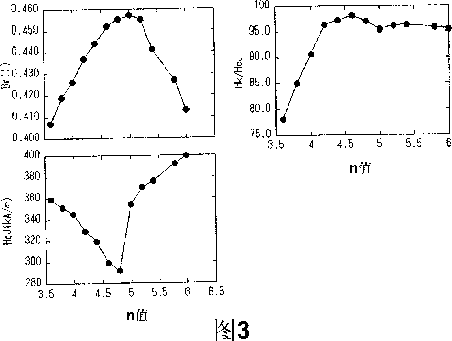
[0100] In formula (1-x)CaO·(x / 2)La 2 o 3 ·(n-y / 2)Fe 2 o 3 - In yCoO, except having set x=0.5, y=0.3, x / y=1.67, and 3.6≤n≤6.0, it carried out similarly to Example 1, and produced the sintered magnet. The magnetic properties of the obtained sintered magnets were measured. Fig. 3 shows the measurement results of residual magnetic flux density Br, coercive force HcJ, and squareness ratio Hk / HcJ with n value as the horizontal axis.

[0101] It can be seen from Figure 3 that in the range of 4.0≤n≤6.0, it shows a high squareness ratio of more than 85%, and in the range of 4.8≤n≤5.8, it shows a high squareness ratio of more than 90%, and further, in the range of 5.0≤ In the range of n≤5.4, high magnetic properties such as Br of 0.44T or higher and HcJ of 340kA / m (4.27kOe) or higher are obtained, and when n=5.2, properties of HcJ of 370kA / m or higher and Br of 0.45T or higher are obtained .

Embodiment 3

[0103] In Example 2, using the composition of n=5.2, the magnetic properties when the sintering temperature is changed between 1150°C and 1190°C are shown in Table 1.

[0104] Sintering temperature

[0105] It can be seen from Table 1 that when the sintering temperature is on the low temperature side, a high HcJ of 370kA / m (4.65kOe) and an Hk / HcJ of more than 95% are obtained; when the sintering temperature is on the high temperature side, a high Br of 0.46T or more and a Hk of more than 90% are obtained. / HcJ.


PUM

PropertyMeasurementUnit
particle sizeaaaaaaaaaa

Abstract

An oxide magnetic material according to the present invention is represented by the formula: (1-x)CaO (x / 2)R 2 O 3 (n-y / 2)Fe 2 O 3 yMO, where R is at least one element selected from the group consisting of La, Nd and Pr and always includes La, M is at least one element selected from the group consisting of Co, Zn, Ni and Mn and always includes Co, and the mole fractions x, y and n satisfy 0.4 |x |0.6, 0.2 |y |0.35, 4 | n | 6, and 1.4 |x / y | 2.5. The oxide magnetic material includes a ferrite having a hexagonal M-type magnetoplumbite structure as a main phase.

Description

technical field [0001] The present invention relates to an oxide magnetic material containing ferrite having an M-type magnetoplumbite structure as a main phase, a sintered magnet, and methods for producing them. Background technique [0002] Ferrite is a general term for compounds composed of divalent cationic metal oxides and trivalent iron. Ferrite magnets are used in various applications such as various rotating machines and speakers. As the material of the ferrite magnet, Sr ferrite (SrFe 12 o 19 ) and Ba ferrite (BaFe 12 o 19 )is widely used. These ferrites are relatively inexpensively produced by powder metallurgy using iron oxide and carbonates such as strontium (Sr) or barium (Ba) as raw materials. [0003] In recent years, it has been proposed that in the above-mentioned Sr ferrite, a part of Sr is substituted with a rare earth element such as La, and a part of Fe is substituted with Co, thereby improving the coercive force HcJ and the residual magnetic flux d...

Claims


Application Information

Patent Timeline
Patent Type & Authority Applications(China)
IPC IPC(8): C04B35/26H01F1/11
CPCH01F1/11C04B35/2633C04B35/2641C04B35/6261C04B35/6262C04B35/62625C04B2235/3208C04B2235/3217C04B2235/3224C04B2235/3227C04B2235/3229C04B2235/3241C04B2235/3262C04B2235/3277C04B2235/3279C04B2235/3284C04B2235/3409C04B2235/3418C04B2235/5445C04B2235/605C04B2235/656C04B2235/6585C04B2235/767C04B2235/785C04B2235/786H01F41/0273
Inventor 小林义德细川诚一丰田幸夫
Owner HITACHI METALS LTD
Why Eureka
Try Eureka