Load detection structure for vehicle seat

a technology for vehicle seats and loading, applied in the direction of instruments, force/torque/work measurement apparatus, material strength using steady bending force, etc., can solve the problems of seat becoming large vertically in size, increasing weight, and prior art being neither realistic nor practical in assembling optimal mechanical structures

Inactive Publication Date: 2004-02-03
TACHI S CO LTD
View PDF7 Cites 36 Cited by
  • Summary
  • Abstract
  • Description
  • Claims
  • Application Information

AI Technical Summary

Benefits of technology

Accordingly, the load detection means is materialized simply by the block member and strain gauge means. Namely, it suffices only to fix one end portion of the block member to a slide rail device and movably connect another end portion of the same with the seat. Thus, the structure is quite much simplified, with a reduced number of required parts, thereby eliminating the assembling steps, making assembly of seat more rapid, and attaining reduction of whole costs involved. The block member may be of a generally oblong shape having a longitudinally elongated body, and therefore it can be attached on and along the foregoing part of movable rail element associated with the slide rail means, thereby avoiding the increase of whole height of the vehicle seat.

Problems solved by technology

However, the Japanese Laid-Open Patent Publication No. 11-001153 has no description on the mechanical structure of load sensor itself, and has no specific teaching on how the load sensor structurally supports the seat and how it actions to detect the seat occupant's weight.
This prior art is therefore neither realistic nor practical in assembling an optimal mechanical structure between the sensor and seat.
The Japanese Laid-Open Patent Publication No. 11-304579 is found defective in that its link mechanism and pivoted arm are complicated in structure and further they occupy much of space heightwise between the seat and slide rail device, which results in the seat becoming large vertically in size and increasing its weight.

Method used


Image

  • Load detection structure for vehicle seat
  • Load detection structure for vehicle seat
  • Load detection structure for vehicle seat

Examples


Embodiment Construction

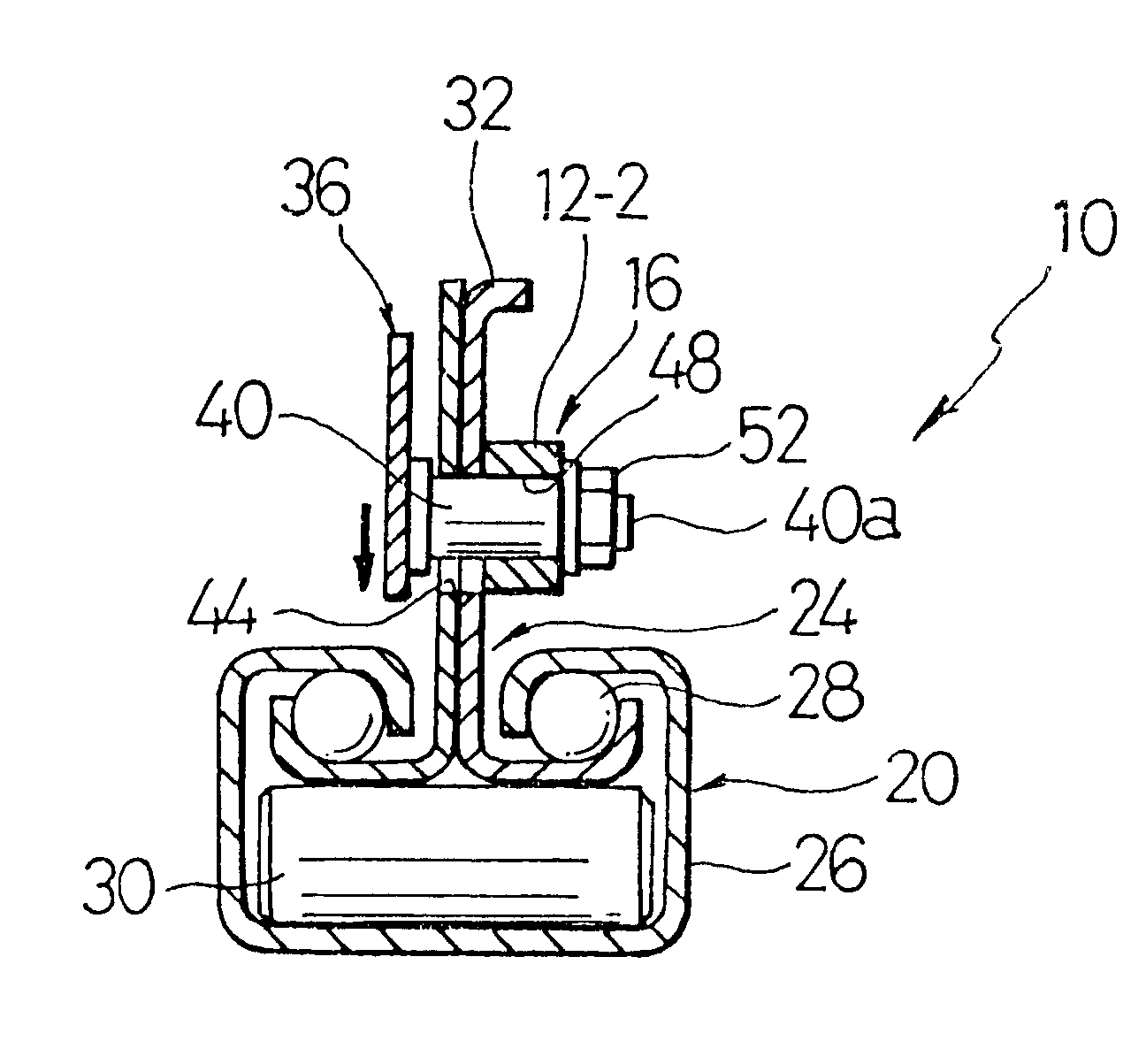
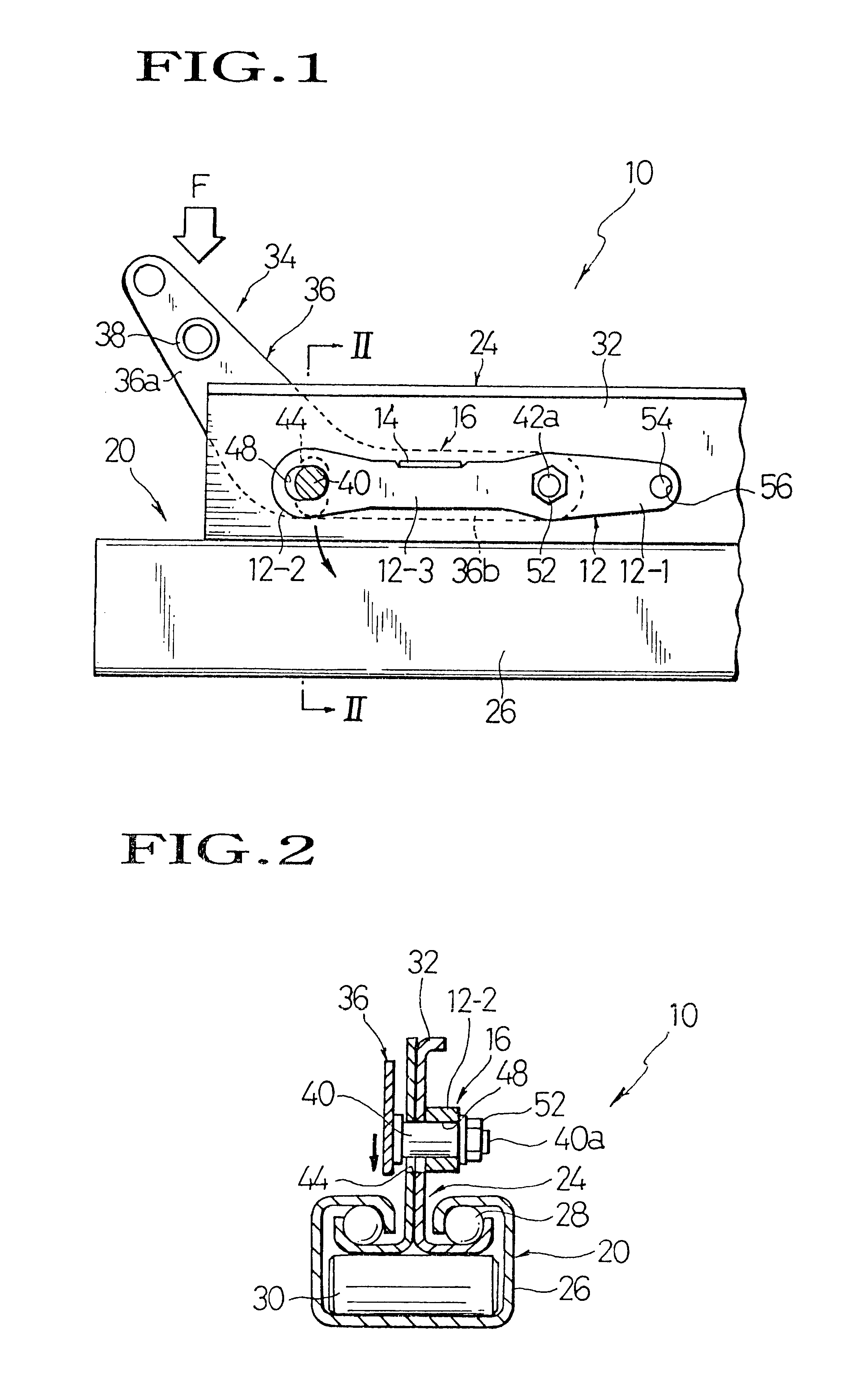
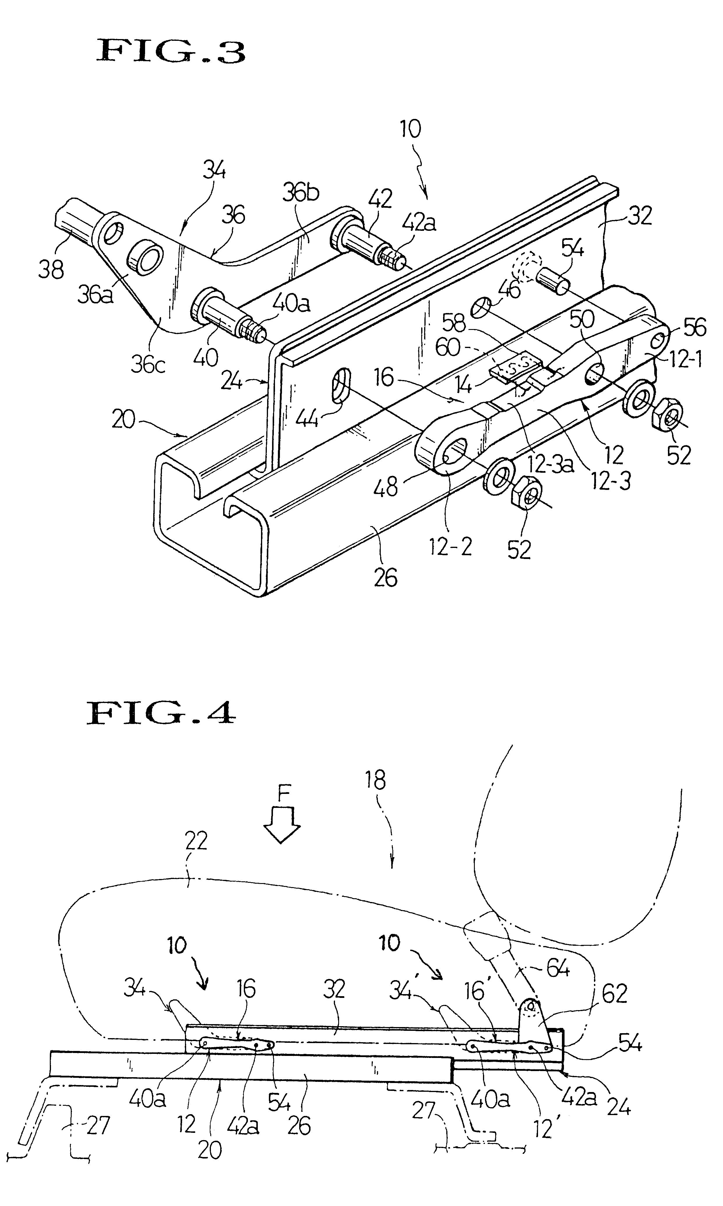
Referring to FIGS. 1 through 4, there is illustrated one preferred mode of load detection structure applicable to a slidable vehicle seat in accordance with the present invention. Reference is first made to FIG. 1 in which designation (10) generally represents a load detection structure provided on a slide rail device (20). As will be elaborated, the load detection structure (10) is basically formed by a load detection means (16) comprising a rigid yet elastic block member (12) and a strain gauge (14) in combination.

As is known, the slide rail device (20) comprises a stationary lower rail (26) to be fixed on a floor side (27) and a movable upper rail (24) slidably fitted in and along the lower rail (26). The typical known configuration of such slide rail device (20) is shown in FIG. 2, wherein the movable upper rail (24) has an upward extension (32) erecting vertically therefrom and a generally inverted-T-shaped base portion slidably accommodated within the lower rail (26) via steel...


PUM

PropertyMeasurementUnit
weightaaaaaaaaaa
total weightaaaaaaaaaa
mechanical structureaaaaaaaaaa

Abstract

A load detection structure in a vehicle seat having a slide rail device provided therewith, which basically comprises a generally oblong block member having a rigid yet resiliently deformable property and a strain gauge attached tight thereon. The block member extends along a part of the slide rail device, such that the deflectable portion thereof is operatively connected with the vehicle seat, while the base portion thereof is fixedly connected with that part of the slide rail device. Hence, a load applied to the seat causes deflection of the deflectable portion of block member, in response to which, the strain gauge detects an amount of such deflection and determines a weight of occupant on the seat.

Description

BACKGROUND OF INVENTION1. Field of the InventionThe present invention relates to a structure allowing for detection of a load applied to a vehicle seat. In particular, the invention is directed to such load detection structure for use in a vehicle seat slidable via a slide device.2. Description of Prior ArtRecent years have witnessed a tendency for various automatically controlled functions and mechanisms to be increasingly incorporated in vehicle or automobiles, including safety devices such as air bags for protecting passengers against a great impact automatically in response to a collision, as well as various kinds of seat position adjustment devices for automatically adjusting the positions of seat sensitive to driver's or passenger's physiques and seating conditions. With such automated control innovations, there have been also found technical improvements to a passenger detection system for detecting the presence and absence of a passenger or driver in a seat of vehicle in adv...

Claims


Application Information

Patent Timeline
Patent Type & Authority Patents(United States)
IPC IPC(8): B60N2/06G01G19/40G01G19/414B60N2/90G01G19/12G01G19/52
CPCB60N2/06G01G19/4142
Inventor MURAISHI, SHOUZOU
Owner TACHI S CO LTD
Why Eureka
Try Eureka