
Friction wedge liner with backing plate

Inactive Publication Date: 2004-03-09
RFPC HLDG CORP
View PDF3 Cites 57 Cited by
  • Summary
  • Abstract
  • Description
  • Claims
  • Application Information

AI Technical Summary

Benefits of technology

It is, therefore, one of the primary objects of the present invention to provide a composition liner with a backing plate for a friction wedge assembly to eliminate the need for bonding the composition material to the cast metal wedge.
Yet another object of the present invention is to provide a composition liner with a backing plate for a friction wedge assembly which will reduce maintenance.

Problems solved by technology

The difficulty encountered with this design has been in obtaining a satisfactory bond of the composition liner to the cast metal wedge.

Method used


Image

  • Friction wedge liner with backing plate
  • Friction wedge liner with backing plate
  • Friction wedge liner with backing plate

Examples


Embodiment Construction

Prior to proceeding with the more detailed description of the present invention it should be noted that, for the sake of clarity, identical components which have identical functions have been designated by identical reference numerals throughout the several views illustrated in the drawings.

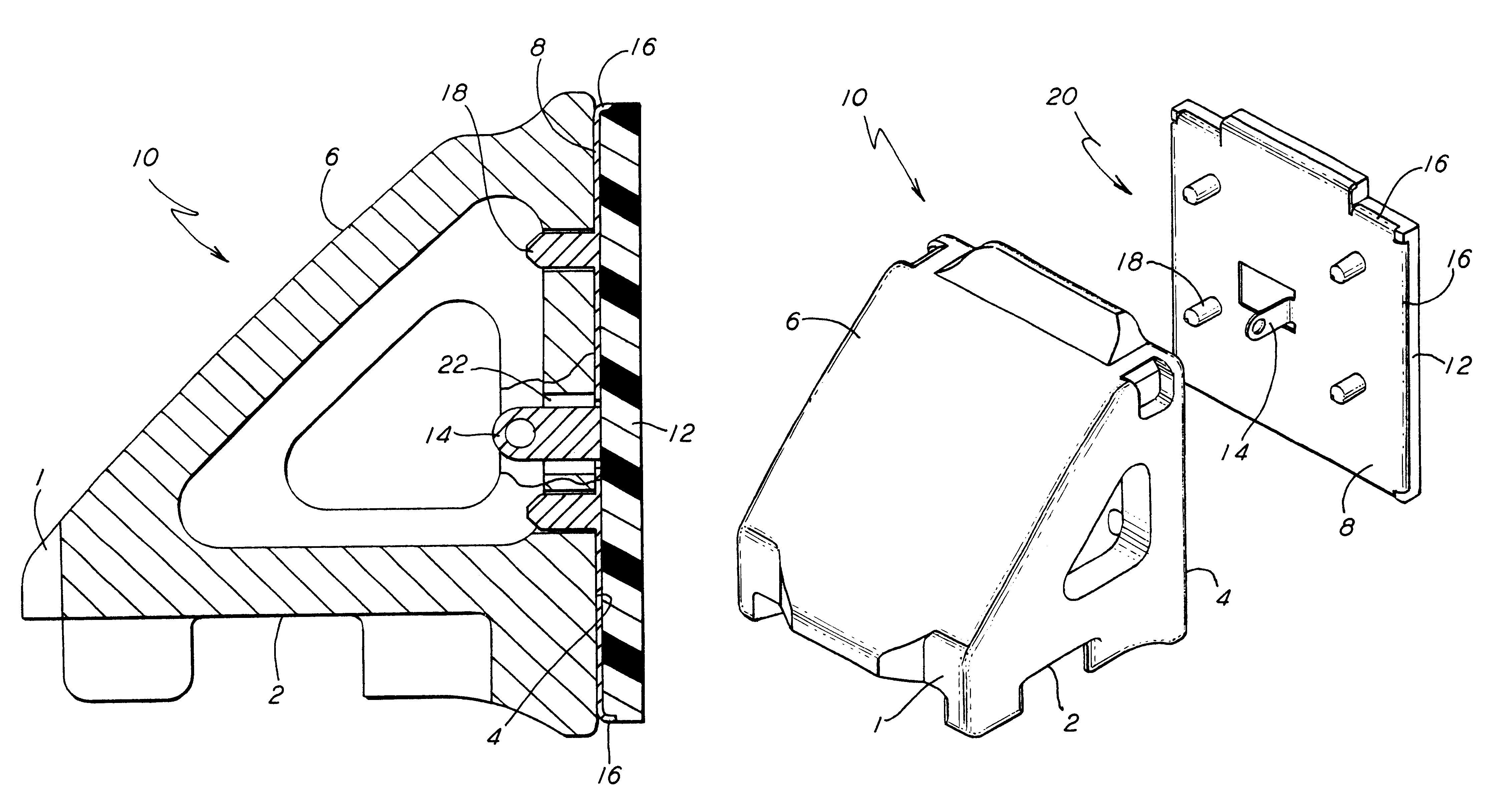
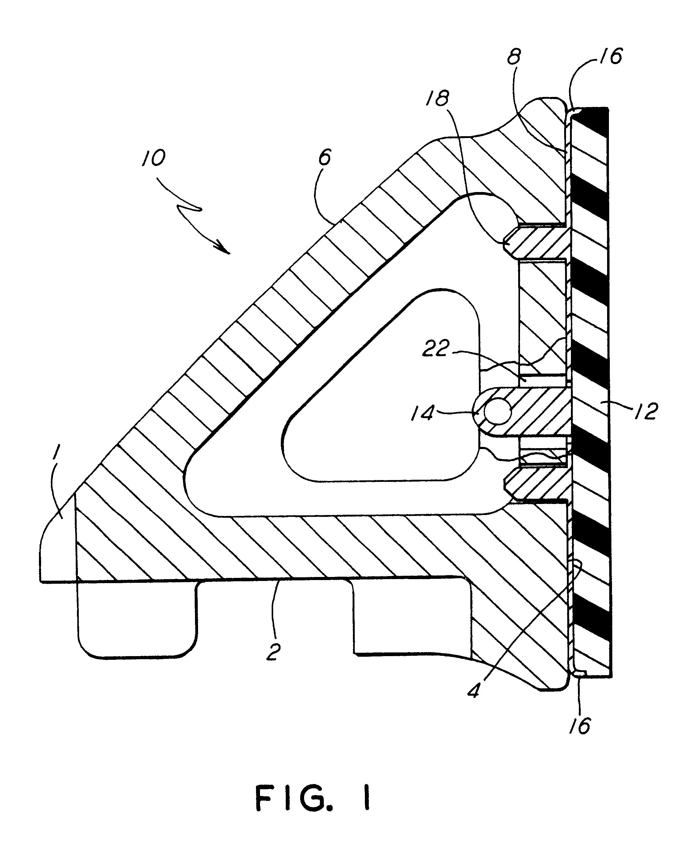
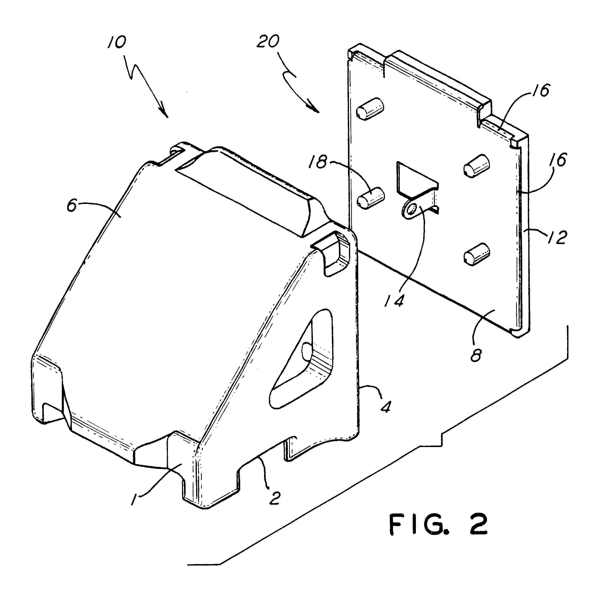
Illustrated in FIGS. 1 and 2 is a friction wedge assembly, generally designated 10, for use in a suspension system of railroad car trucks. Such friction wedge assembly 10 includes is a cast metal wedge 1 that has a bottom face 2, a vertical face 4 that is substantially perpendicular to the bottom face 2 and a sloped face 6. The sloped face 6 contacts a mating surface on a bolster of such railroad car truck (not shown). Although it is presently preferred that such wedge 1 be a metal casting it is within the scope of the invention that such wedge 1 be of other material.

The present invention provides a metal backing plate 8 that has a first side that is removably engageable with the vertical face 4 ...


PUM


Abstract

A friction wedge assembly for use in a suspension system of railroad car trucks. The friction wedge assembly comprises a cast metal wedge having a bottom face, a vertical face that is substantially perpendicular to the bottom face and a sloped face for contacting a mating surface on a bolster of such railroad car truck. There is a metal backing plate that has a first side removably engageable with the vertical face of the cast metal wedge, a means for securing the metal backing plate to the cast metal wedge and a composition liner disposed on a second side of the metal backing plate for engaging such metal wear liner on such side frame of such railroad car truck.

Description

The present invention relates, in general, to a wedge shaped friction casting that serves as a shock absorber in the suspension of railroad cars and, more particularly, the present invention relates to a composition liner bonded to a backing plate for such wedge shaped friction casting.The suspension of railroad trucks include a wedge shaped friction casting which serves as a shock absorber. The wedge is supported by a spring and works between the bolster and the side frame. The sloped face of the wedge maintains contact with a mating face of the bolster while the vertical face of the wedge slides against a metal wear liner on the side frame. The spring pushes on the bottom face of the wedge thereby providing the load to force the wedge between the bolster and the side frame. The friction between the wedge and the side frame wear plate provides damping for the truck suspension.Certain truck designs use a wedge with a composition friction liner bonded to the vertical face of the wedg...

Claims


Application Information

Patent Timeline
Patent Type & Authority Patents(United States)
IPC IPC(8): B61F5/12B61F5/02
CPCB61F5/122
Inventor MCCABE, THOMAS W.FORMOLO, JOSEPH F.SHUTE, BRUCE W.
Owner RFPC HLDG CORP
Learn More