Roll forming machine

Inactive Publication Date: 2004-03-09
AIRBUS OPERATIONS LTD
View PDF23 Cites 49 Cited by
  • Summary
  • Abstract
  • Description
  • Claims
  • Application Information

AI Technical Summary

Problems solved by technology

When roll forming the material, corners are generally radiussed as it is not normally possible to form a corner with a precise sharp edge.

Method used


Image

  • Roll forming machine
  • Roll forming machine
  • Roll forming machine

Examples


Embodiment Construction

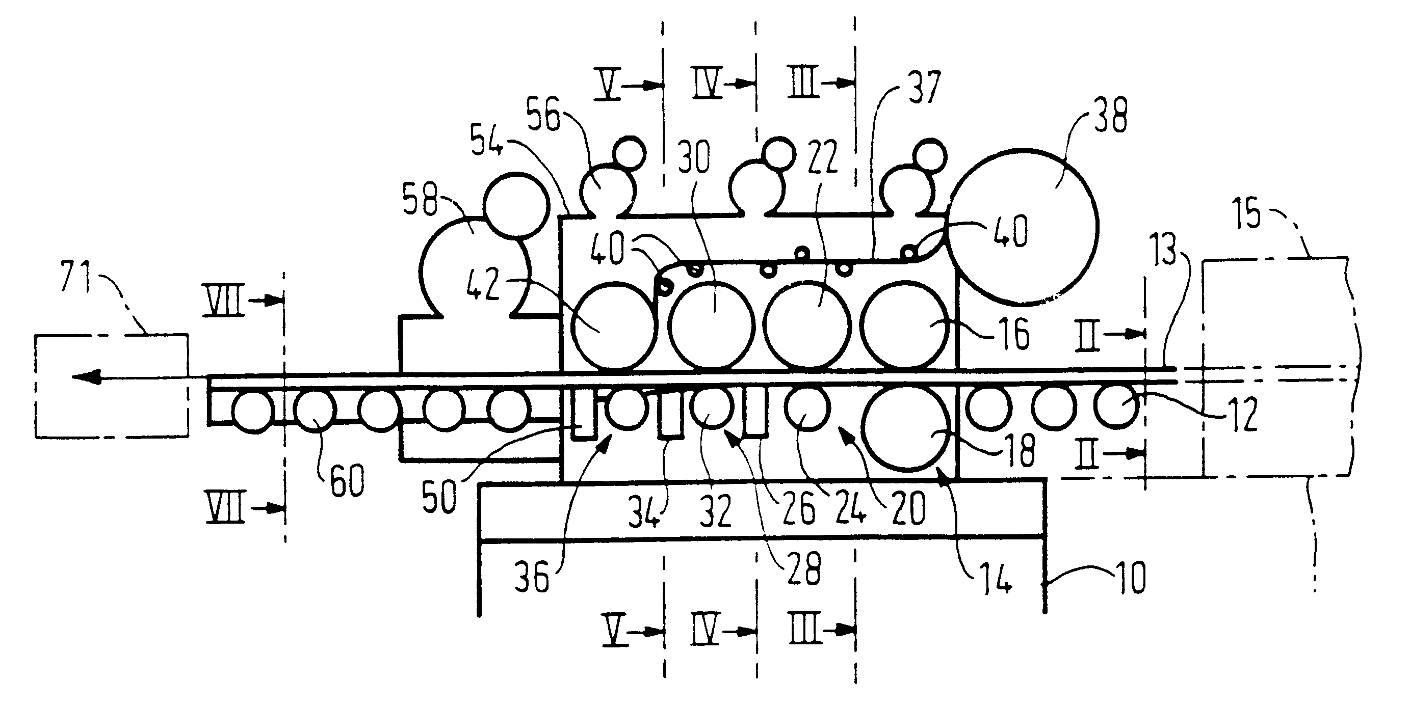
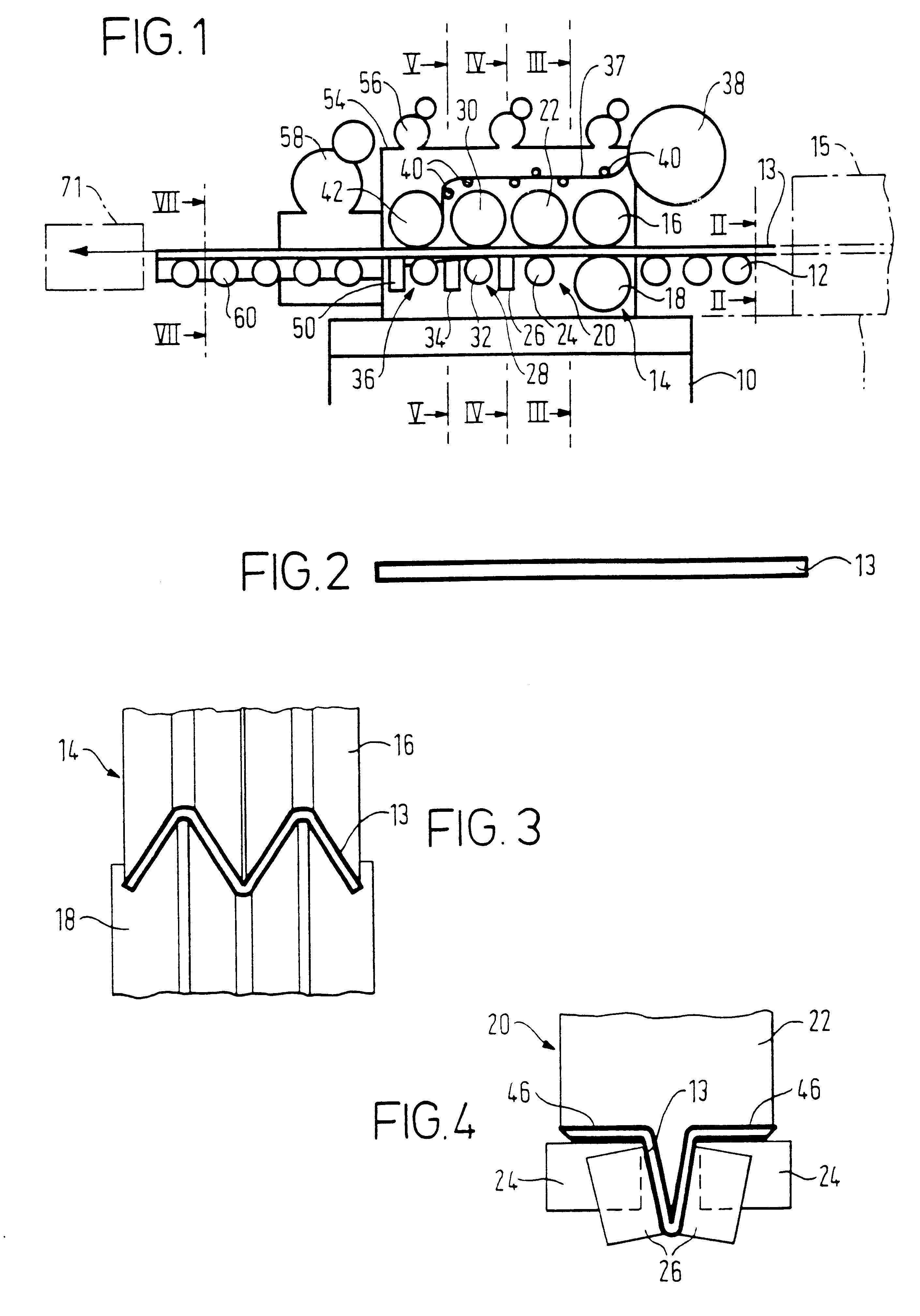
Referring to FIG. 1, the machine comprises a floor-mounted bed 10 on which a multiplicity of rollers is mounted. In FIG. 1, three upstream rollers 12 support a laminate 13 as it enters the roll forming machine. The laminate 13 is a lay-up of carbon fiber fabrics pre-impregnated with an uncured epoxy matrix. In the uncured form, the laminate 13 is semi-rigid. The laminate 13 may be produced at a lay-up station 15 immediately upstream of the rollers 12. In such a case the rollers 12 may serve as a conveyor for the laminate 13 leaving the lay-up station 15.

The laminate 13 passes through a first set of shaping rollers 14 comprising upper and lower rollers 16, 18. The rollers 16, 18 have W shaped peripheries which fit one within the other as shown in FIG. 3 with a nip between. The rollers 16, 18 form the laminate into an inverted W shape.

Next, the laminate passes through a second set of shaping rollers 20 comprising an upper roller 22 and two spaced apart lower rollers 24. Also, the set ...


PUM

PropertyMeasurementUnit
speedaaaaaaaaaa
speedaaaaaaaaaa
lengthaaaaaaaaaa

Abstract

The roll forming machine comprise a series of rollers 14, 20, 28 and 36 for shaping a fabric 13 such as a fabric impregnated with a curable matrix. A feed roller 36 is provided for feeding a length of material 37 such as a tow of fibres onto the fabric during or subsequent to the shaping process. The roll forming process is particularly useful in the manufacture of blade stiffeners for an aircraft wing.

Description

1. Field of the InventionThe invention relates to a roll forming machine and method and is particularly, but not exclusively, concerned with the production of a roll formed component for an aircraft.2. Discussion of Prior ArtWhere roll forming of components is effected on a machine, material passing through the machine is shaped by deforming and, in some cases, surfaces of the material are pressed together and webs and flanges are formed. When roll forming the material, corners are generally radiussed as it is not normally possible to form a corner with a precise sharp edge. Sometimes, where the radius is next to an adjacent radius or surface an unwanted recess is defined. Also, when manufacturing aircraft components such as wings, a lay-up of fabric such as carbon fiber is sometimes used to form the wing skin. Certain areas of the wing skin may be stiffened on the internal surfaces by means of blade stiffeners of T-shape cross section. Where a lay-up of fabric is used to produce th...

Claims


Application Information

Patent Timeline
Patent Type & Authority Patents(United States)
IPC IPC(8): B29C53/04B29C53/00B29C70/04B29C70/50B29C70/06D06C15/00
CPCB29C53/043B29C70/504B29D99/0003B29C70/541
Inventor BURLEY, GRAHAM J.WILLIAMS, STEPHENKAYE, ALLAN J.
Owner AIRBUS OPERATIONS LTD
Why Eureka
Try Eureka