Calender

a calender and calender technology, applied in the field of calenders, can solve the problems of forming oscillatory parts, l-stands are not suitable for higher operating speeds and larger widths, and are not suitable for larger widths,

Inactive Publication Date: 2004-03-16
VOITH PATENT GMBH
View PDF13 Cites 1 Cited by
  • Summary
  • Abstract
  • Description
  • Claims
  • Application Information

AI Technical Summary

Benefits of technology

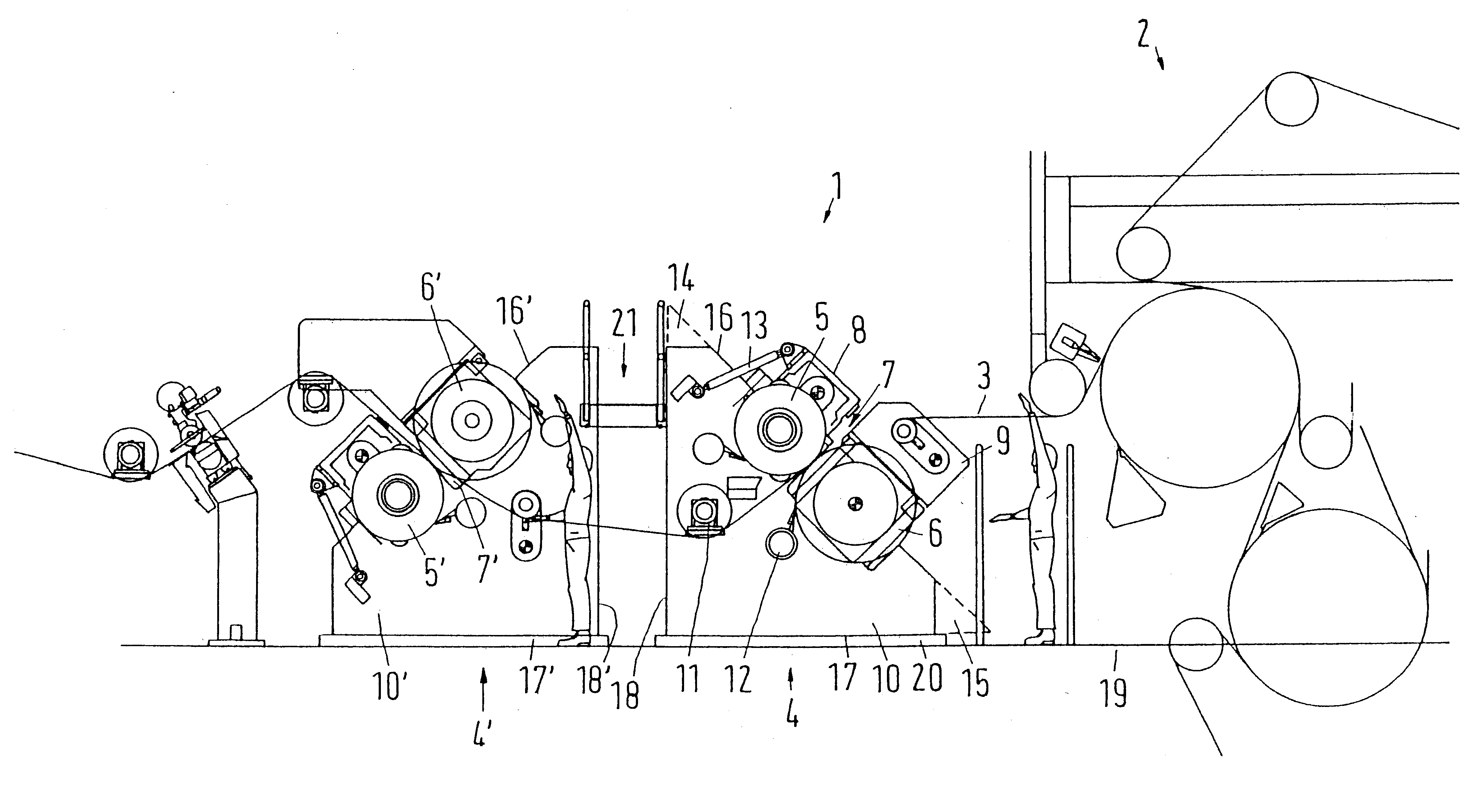
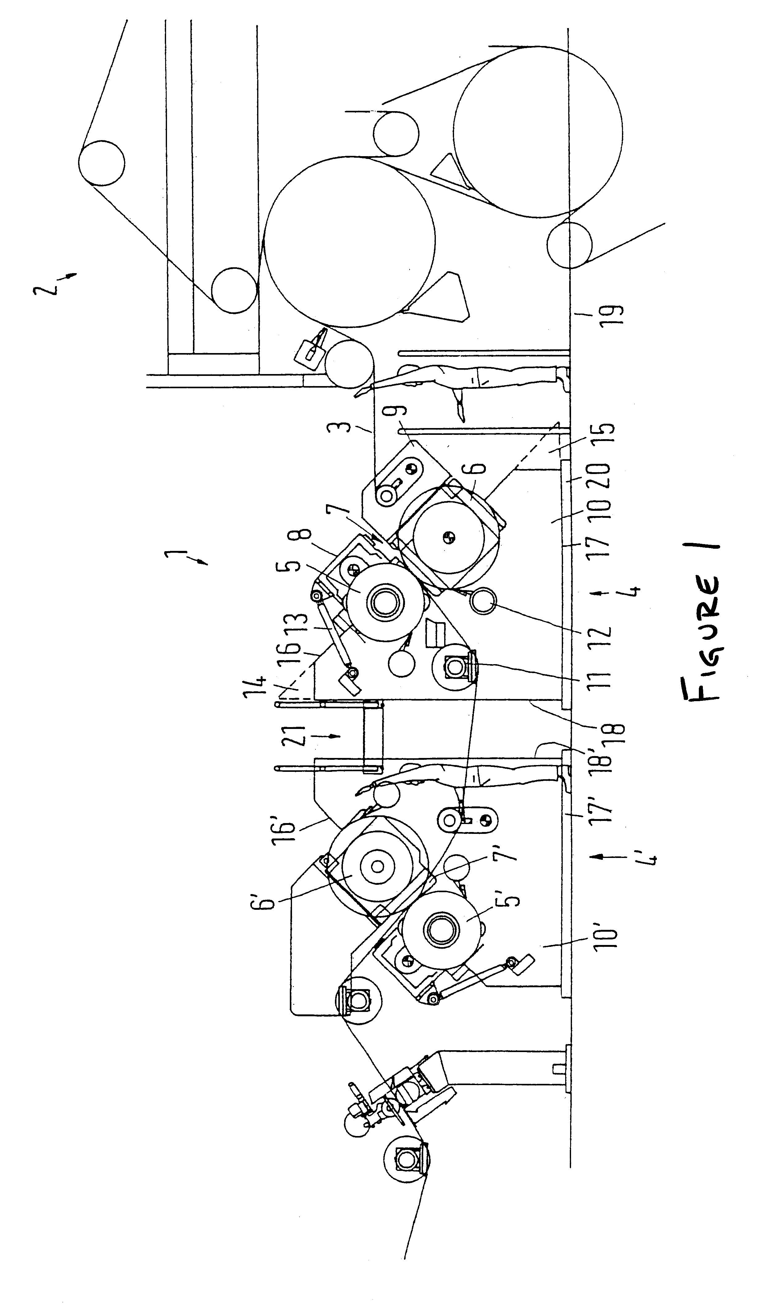
The instant invention contemplates a roll stack tilted at an angle, i.e., inclined to the vertical. A preferred angle of tilt is about 45.degree. which, however, can be changed within the scope of the values given above. As a result of the instant structural arrangement, a partial load alleviation, i.e., the specific weight of the upper roll no longer acts on the line load in the nip to the full extent. However, there is still a vertical roll weight component that leads to a minimum load on the antifriction bearings, so that its play does not lead to increased vibration behavior of the rolls. Due to the tilt, the rolls of the roll stack can again be handled by a crane, i.e., to be dismantled and / or installed. Despite these easy possibilities for changing a roll, a high operating speed and a large working width are rendered possible by the special construction of the stands. The stands have a very wide bearing surface that is the result of the contact edge supporting the bearing edge over its entire length. This support is implemented by a plate so that no hinge points or other connection points are formed between the contact edge and the bearing edge that could be distorted in a critical way. Thus, the plate provides the stand with an extraordinarily high degree of rigidity. Although the stand extends further in the flat (horizontal) direction due to the tilt of the bearing edge relative to the vertical, the total height is reduced.
The plate can include openings as needed for assembly or maintenance purposes. However, as a whole, it may be preferable that the plate be formed as an essentially flat form which accordingly provides a high mechanical stability. The rolls can be supported in a leverless manner, i.e., they can either be displaced parallel to the bearing surface or they can be rolls with jacket lift.
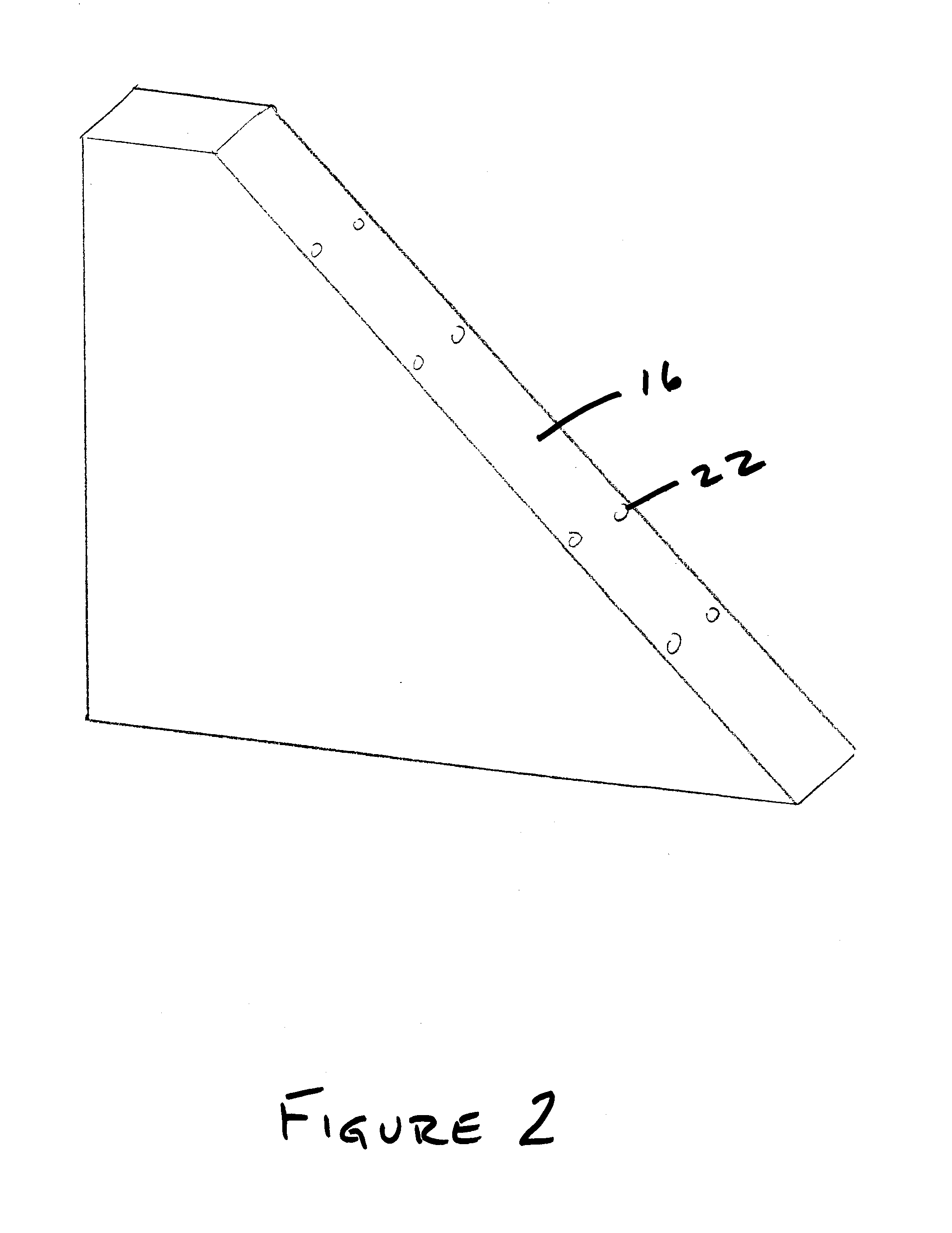
The plate preferably includes a thickness of at least about 150 mm, and more preferably of at least about 200 mm. The choice of a relatively "thick" plate has several advantages: high mechanical stability results, and a sufficiently large area is available in the bearing edge to provide mounting openings for the antifriction bearings or to other attachment parts. A stand embodied or formed in this way is considerably more rigid than previously known stands, which utilized columns and tie-bars to form a box-frame construction, i.e., by welding together in box form comparatively thin metal sheets with a thickness in the range of about 20 mm.
The plate is preferably formed by a sheet metal that essentially includes a triangular shape. The term "sheet metal" is intended to also cover metal plates with the above-mentioned thickness range according to the invention. Such a triangle is easy to produce, since only a few cuts are necessary to determine the triangular shape. Furthermore, it results in a pleasing appearance.
Two roll stacks are preferably provided, and each stack includes a plate-like stand with an essentially triangular shape with connecting edges substantially vertically oriented at each axial end. Moreover, the two roll stacks may preferably be positioned adjacent to one another. This arrangement of two roll stacks is known per se, and makes it possible for the material web to first rest with its first side on a hard roll and with its opposite second side on a soft roll, i.e., a roll with an elastic or resilient surface, while in the next roll stack the conditions are exactly reversed, i.e. the second side rests on the soft roll and the first side on the hard roll. Of course, it is also possible to use only rolls with the same type of surface in each roll stack. If the connecting edges are substantially vertically oriented and the stands placed mirror-inverted or mirror-symmetrical to each other, the stands can be positioned with a relatively small distance between them, thereby keeping the required construction space small.

Problems solved by technology

However, it has been shown that the L-stand is not suitable for higher operating speeds and larger widths.
Experience shows that there is a risk of vibration problems at speeds of over about 1200 m / min and widths of over about 7 m.
In this regard, it is assumed that the points of a triangle do not contribute much to the stability of the stand, but instead represent a risk of forming oscillatory parts.

Method used


Image

  • Calender
  • Calender
  • Calender

Examples


Embodiment Construction

The particulars shown herein are by way of example and for purposes of illustrative discussion of the embodiments of the present invention only and are presented in the cause of providing what is believed to be the most useful and readily understood description of the principles and conceptual aspects of the present invention. In this regard, no attempt is made to show structural details of the present invention in more detail than is necessary for the fundamental understanding of the present invention, the description taken with the drawings making apparent to those skilled in the art how the several forms of the present invention may be embodied in practice.

A calender 1 is arranged at an outlet of a paper machine 2 (shown only in diagrammatic form) to glaze a web 3 coming out of paper machine 2.

To this end, calender 1 includes a first roll stack 4 with a hard roll 5 and a soft roll 6. The hard roll 5 is made of metal and features a hard, but very smooth surface. Soft roll 6 includ...


PUM


Abstract

Calender including at least one roll stack having a plurality of rolls arranged to form at least one nip, a stand arrangement having a stand located at each axial end of the at least one roll stack, and antifriction bearings arranged to support the plurality of rolls on the stand arrangement. Each stand includes a bearing edge on which the antifriction bearings are arranged, a contact edge structured and arranged to contact a mounting surface, and a connecting edge forming a connection between the bearing edge and the contact edge. Each stand further includes a plate structured and arranged to include the bearing edge, the contact edge and the connecting edge to one another.

Description

The present application claims priority under 35 U.S.C. .sctn.119 of German Patent Application No. 101 29 102.7, filed on Jun. 16, 2001, the disclosure of which is expressly incorporated by reference herein in its entirety.1. Field of the InventionThe present invention relates to a calender with at least one roll stack having a maximum of three rolls arranged to form at least one nip limited by two rolls, and with a stand arrangement featuring a stand at each axial end of the roll stack. The rolls are supported on the stand with the aid of antifriction bearings.Such a calender, which is also called a "soft calender," is used mainly in paper production. Since it features only one or two nips per roll stack, it is particularly suitable as a machine calender which can be used in-line, i.e., directly following a paper machine.2. Discussion of Background InformationA known calender of the type mentioned at the outset features an essentially perpendicular (vertical) standing roll stack wi...

Claims


Application Information

Patent Timeline
Patent Type & Authority Patents(United States)
IPC IPC(8): D21G1/00
CPCD21G1/00
Inventor CONRAD, HANS-ROLF
Owner VOITH PATENT GMBH
Why Eureka
Try Eureka