Wire straightening and cut-off machine and process

a cutting-off machine and wire technology, applied in the field of wire straightening and cutting-off machines and processes, can solve the problems of insufficient, complicated, bulky, and/or expensive conventional techniques addressing this particular application

Inactive Publication Date: 2004-03-16
WIESENFELD YAIR
View PDF7 Cites 16 Cited by
  • Summary
  • Abstract
  • Description
  • Claims
  • Application Information

AI Technical Summary

Problems solved by technology

Conventional techniques addressing this particular application

Method used


Image

  • Wire straightening and cut-off machine and process
  • Wire straightening and cut-off machine and process
  • Wire straightening and cut-off machine and process

Examples


Embodiment Construction

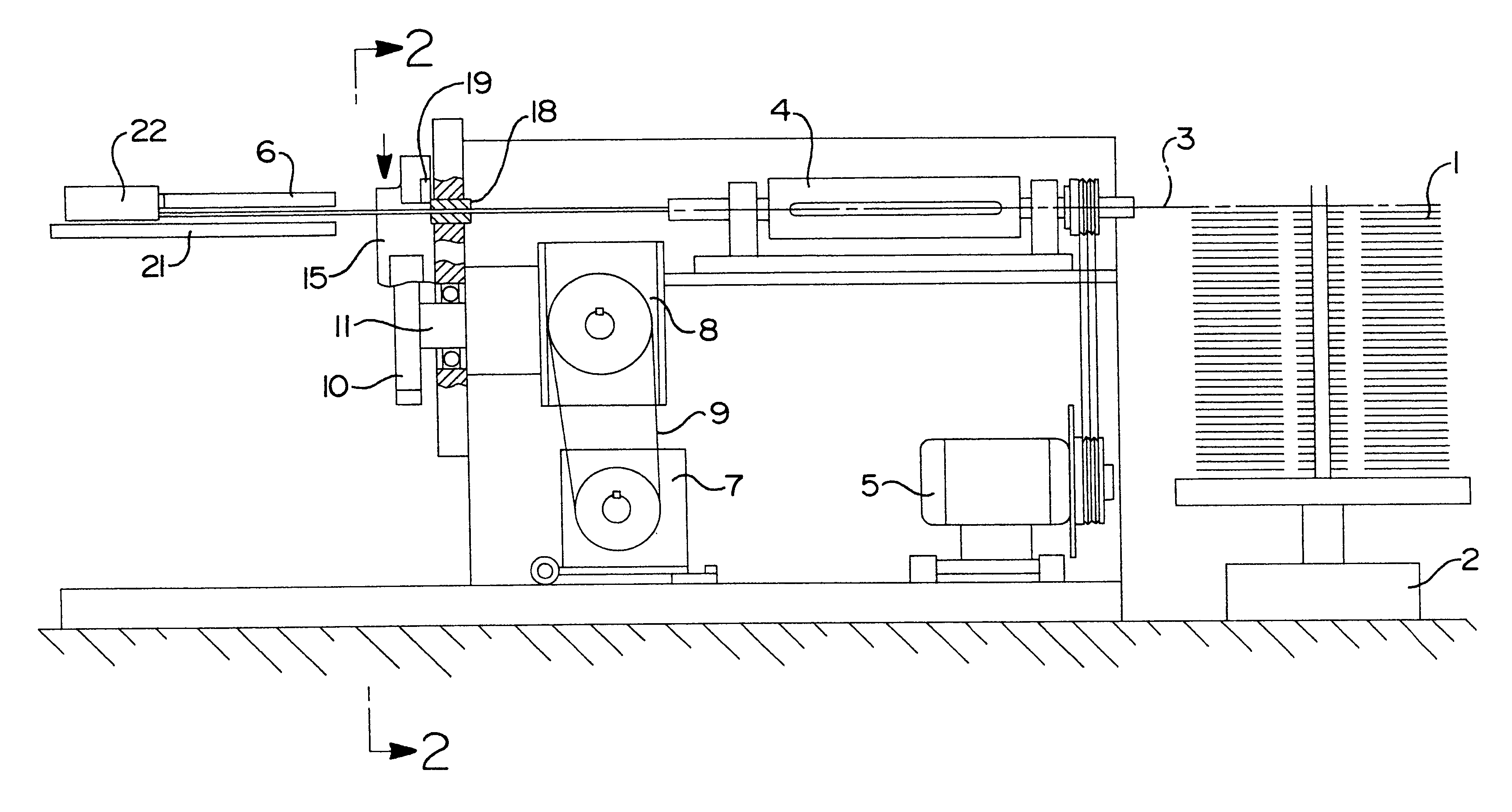
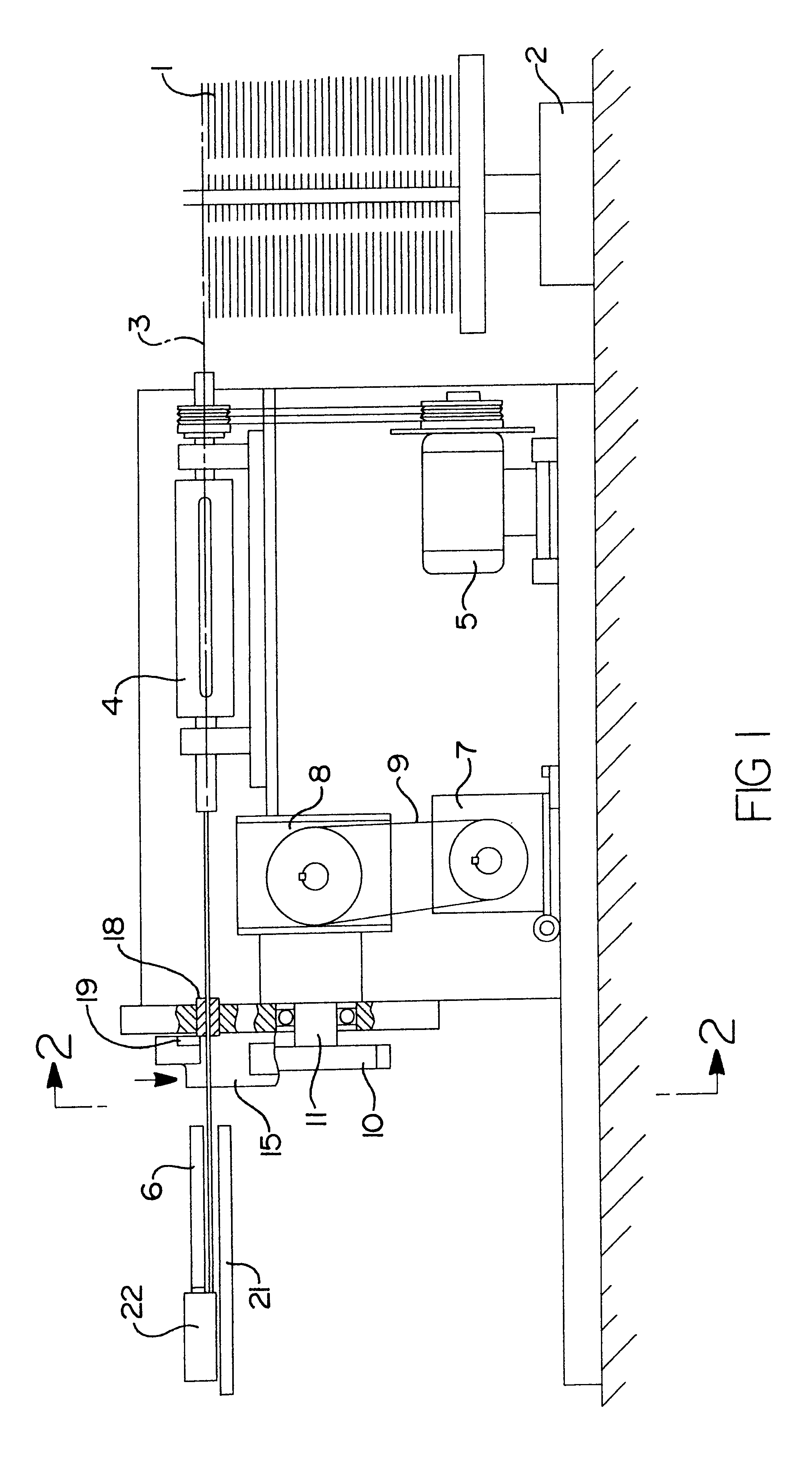
With reference to FIGS. 1 and 2, there is shown a preferred embodiment of the present invention employed in a wire straightening and cut-off machine.

As illustrated in FIG. 1, a wire coil 1 is disposed on an uncoiler 2. Alternatively, the wire 3 may be supplied in bars or in any other suitable form.

The wire 3 from the wire coil 1 passes to and through a wire straightener and feeder unit 4. A straightener motor 5 drives the wire straightener and feeder unit 4. The wire straightener and feeder unit 4 includes a suitable feeder device and a straightener device. The feed device controls the speed at which the wire 3 moves or is fed through the machine.

After the wire 3 has been straightened, the wire 3 travels to the cut-off system and along a run-off guide 6.

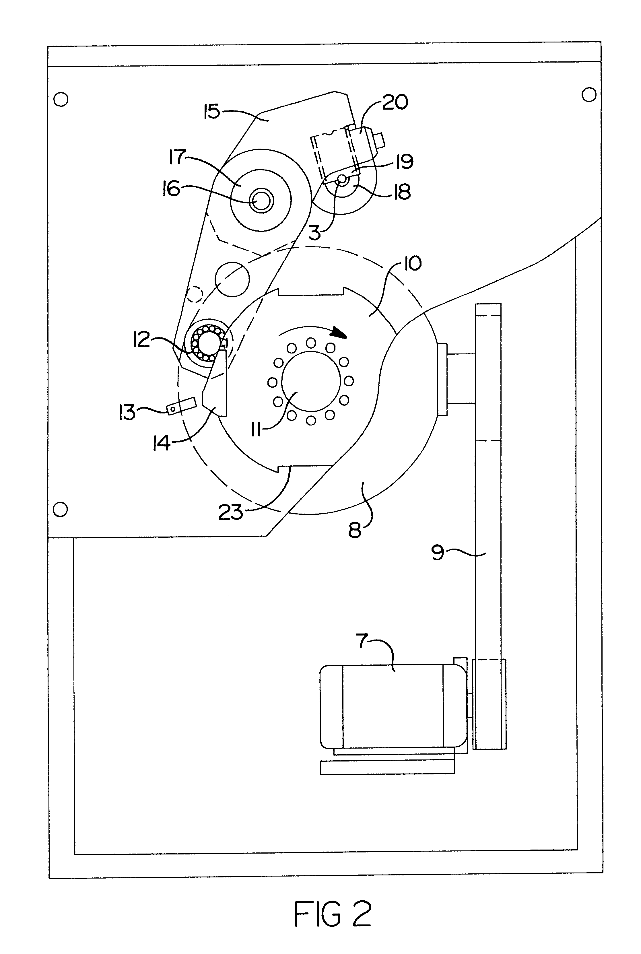
The cut-off system includes a servomotor 7, a mechanical reduction gear 8, a timing belt 9 or other drive means, a rotating disc 10 mounted on a main spindle or output shaft 11, a cam follower 12, a microswitch or proximity sensor 13...


PUM

PropertyMeasurementUnit
Timeaaaaaaaaaa
Speedaaaaaaaaaa

Abstract

A wire straightening and cut-off process and machine which feeds, straightens, and cuts wire, and which uses a servomotor in dual mode. In a continuous mode, short wire parts are cut at a high cut-off rate. In an intermittent mode, long wire parts are cut wherein each cut is triggered by a signal.

Description

The present invention relates generally to a wire straightening and cut-off machine and process. In particular, the present invention relates to a machine and process which uses a servomotor in a dual mode, wherein the servomotor may be used as a regular motor in a continuous mode or operation, and / or may be used as a servomotor in an intermittent mode or operation.BACKGROUND OF THE INVENTION AND DESCRIPTION OF THE RELEVANT ARTThe present invention has a plethora of applications, and is particularly suitable for use in a straightening and cut-off machine application which is used to feed, straighten, and cut wire.Conventional techniques addressing this particular application have proved inadequate, complicated, bulky, and / or expensive.The relevant art is exemplified by the following United States patents.U.S. Pat. No. 4,391,307 issued in 1983 to Levi et al. entitled "WIRE STRAIGHTENING AND CUTTING MECHANISM" discloses a cutting mechanism correlated with the driving of feed rolls to ...

Claims


Application Information

Patent Timeline
IPC IPC(8): B21F11/00B21F1/02B21F1/00B23D17/00B23D17/02B23D36/00
CPCB21F1/026B21F11/00B23D17/02B23D36/00B23D36/0041B23D36/0058Y10T83/4691
Inventor WIESENFELD, YAIR
Owner WIESENFELD YAIR
Why Eureka
Try Eureka