Device for upper extremity elevation

Inactive Publication Date: 2004-03-23
UNITED STATES OF AMERICA THE AS REPRESENTED BY THE SEC OF THE ARMY
View PDF30 Cites 48 Cited by
  • Summary
  • Abstract
  • Description
  • Claims
  • Application Information

AI Technical Summary

Benefits of technology

Another advantage of the invention is that it is more ergonomical than the prior art devices.
Another advantage of the invention is the flexibility that will be allowed in future purchases of beds and chairs, because of the attachment range of the bracket.
A further advantage of the invention is the durability of the preferred construction of the invention.
A further adva

Problems solved by technology

The prior art device and jerry rigged devices used by the inventors provided less flexibility in terms of what the devices could attach to in terms of different beds and chairs.
The prior art device offered only a limited range of adjustments.
The prior art devices easily rusted because of their steel construction or broke during use because of poor design.
This type of sling will apply pressure over a greater area of the slinged body part such that if the patient has a burn this may lead to further complications resul

Method used


Image

  • Device for upper extremity elevation
  • Device for upper extremity elevation
  • Device for upper extremity elevation

Examples


Embodiment Construction

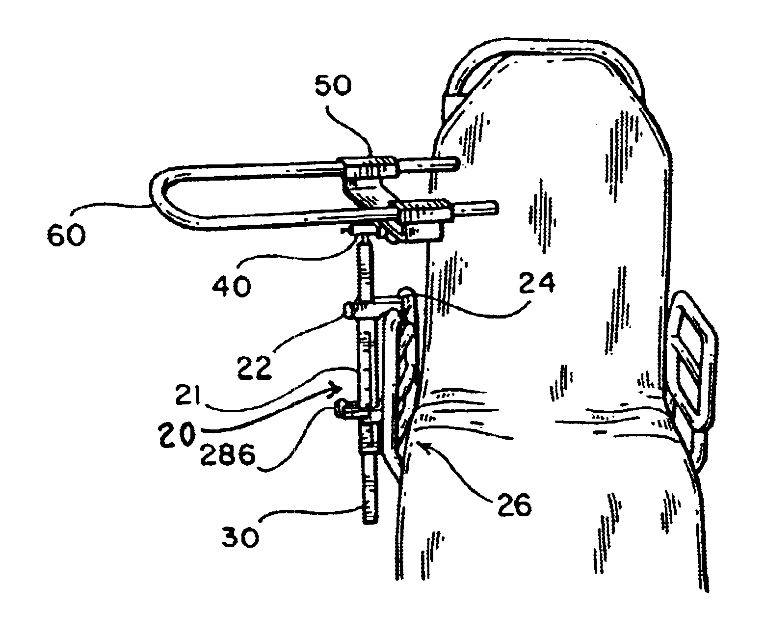
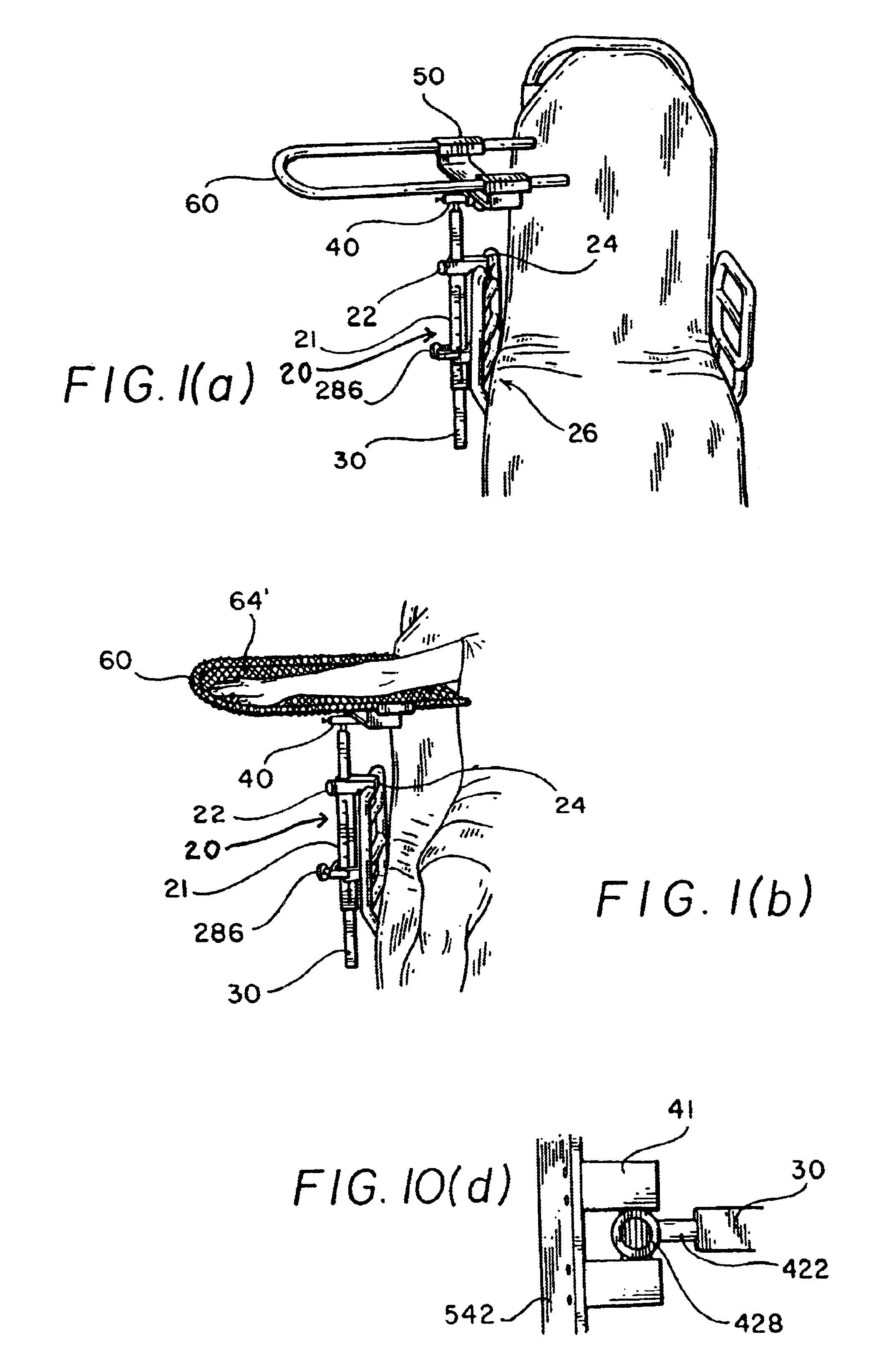
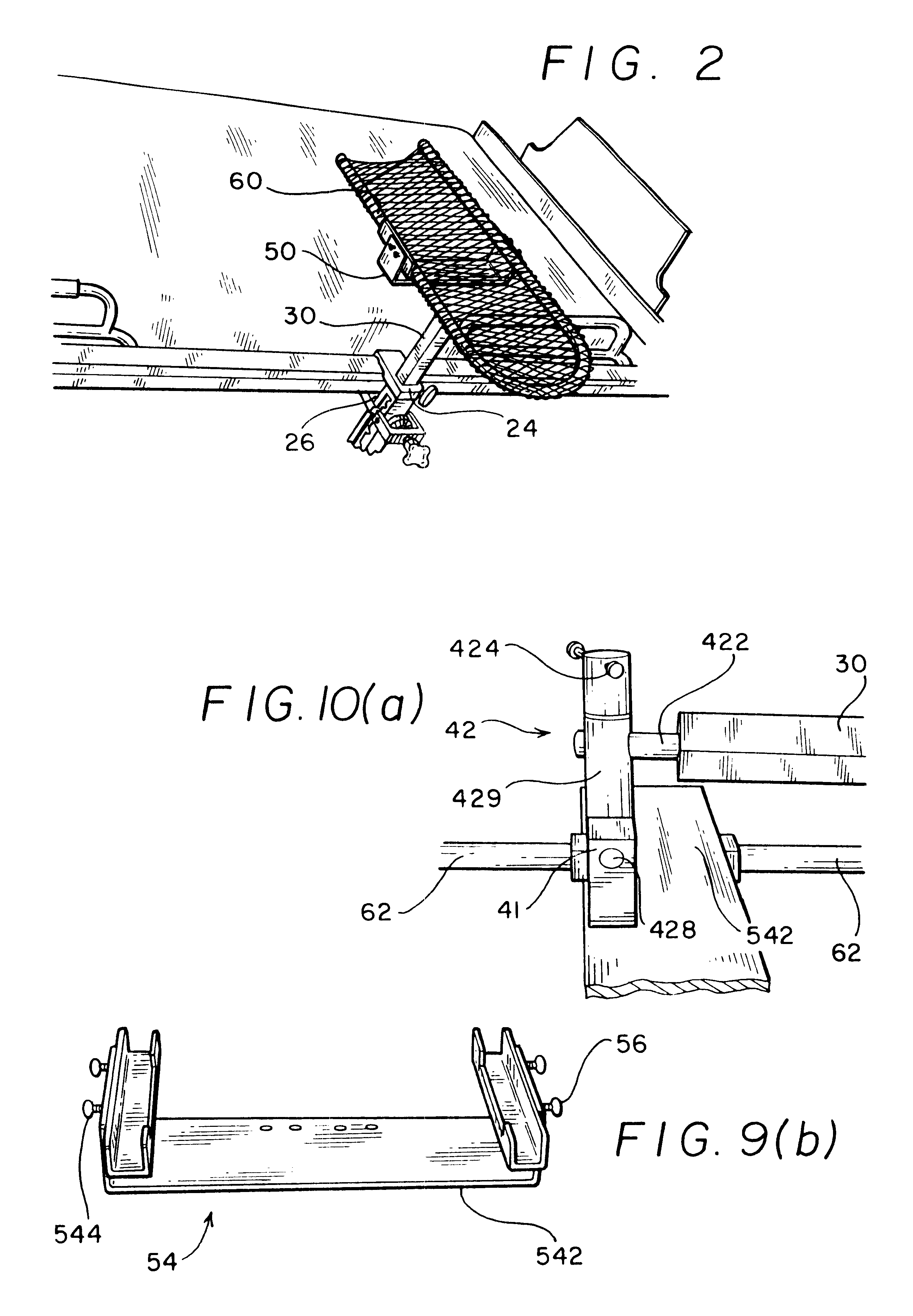
FIGS. 1(a)-2 illustrates an embodiment of the invention installed on typical hospital patient care equipment. FIGS. 2-7(c) illustrate a preferred embodiment of the invention. In accordance with the present invention, the apparatus preferably includes a bracket 20 (or clamp means), a pole 30, a knee joint 40, a cradle 50, and an extremity support 60.

The support 60 preferably includes a U-shape bar 62 with a member 64 running along its length and between the two legs of the bar 62 as illustrated in FIG. 3(a). The member 64 preferably has a concave surface along its length such that a channel is formed along its length as illustrated in FIG. 3(b). The member 64 preferably is covered with padding 66 so that an individual's arm rests on the padding as illustrated in FIG. 3(b). An alternative embodiment is to have the member be meshed or to include an array of punched holes. Additionally, the member 64 preferably will include a folded over edge to prevent the edges of the member 64 from c...


PUM


Abstract

The device is used for supporting an upper extremity limb of a patient located in either a bed or a chair. The device preferably includes bracket, a pole, a knee joint, a cradle, and an extremity support. Preferably, the knee joint provides movement in three radial directions to allow for optimal placement of the extremity support for a particular patient. The bracket preferably provides the flexibility to attach to a wide variety of furniture.

Description

I. FIELD OF THE INVENTIONThis invention preferably relates to a support system for attachment to different beds and chairs. More particularly, the device preferably is a support structure attached to a cradle connected to a knee joint attached to a pole attached to a bracket, which then attaches to either a bed or a chair in which a patient is located who requires his / her extremities to be supported.II. BACKGROUND OF THE INVENTIONThe prior art device and jerry rigged devices used by the inventors provided less flexibility in terms of what the devices could attach to in terms of different beds and chairs. The prior art device offered only a limited range of adjustments. The prior art devices easily rusted because of their steel construction or broke during use because of poor design.When the prior art device was unable to attach to a particular chair or bed frame, a jerry-rig setup was used. The usual design was to use IV poles with a sling hanging from it. The purpose of a sling is ...

Claims


Application Information

Patent Timeline
IPC IPC(8): A61G5/00A61G5/12A61G7/05A61G7/075A61G15/12A61G15/00
CPCA61G5/12A61G7/075A61G15/12A61G2005/125A61G5/125
Inventor SMEED, ERIC M.
Owner UNITED STATES OF AMERICA THE AS REPRESENTED BY THE SEC OF THE ARMY
Why Eureka
Try Eureka