

Feedforward amplifier
a technology of amplifier and feedforward, which is applied in the direction of amplifier, amplifier, amplifier modification to reduce noise influence, etc., can solve the problems of device not working, reducing efficiency, and reducing output power
- Summary
- Abstract
- Description
- Claims
- Application Information
AI Technical Summary
Problems solved by technology
Method used
Image

Examples
embodiment 1
(Embodiment 1)
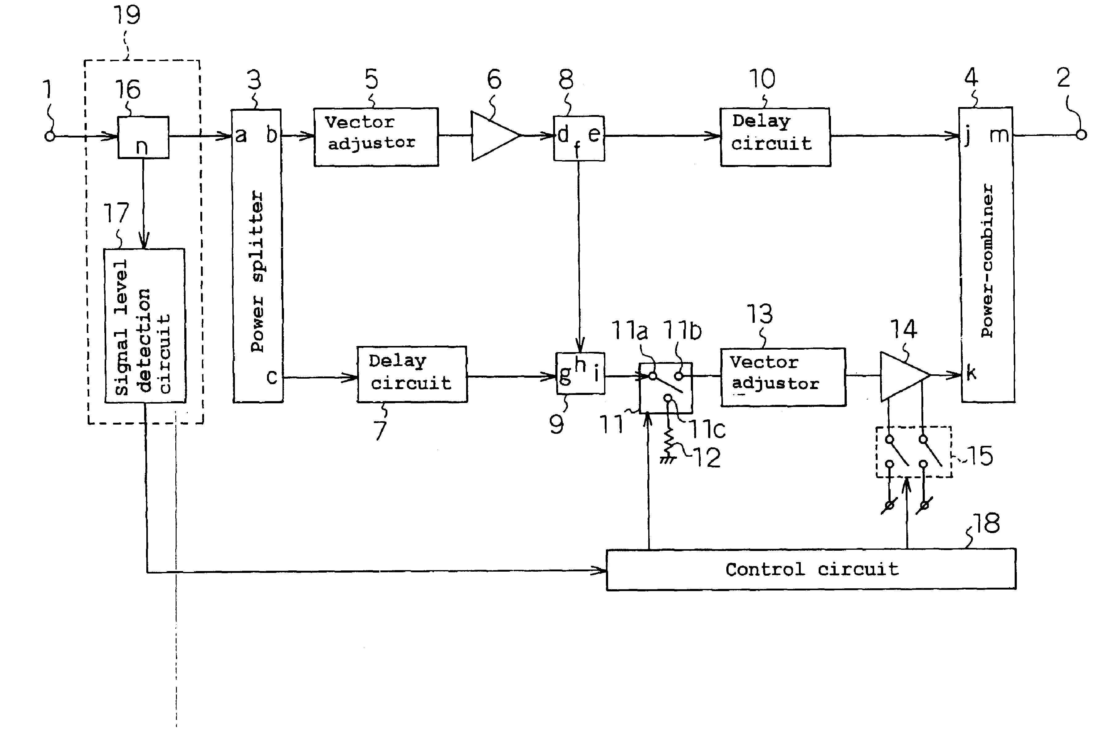
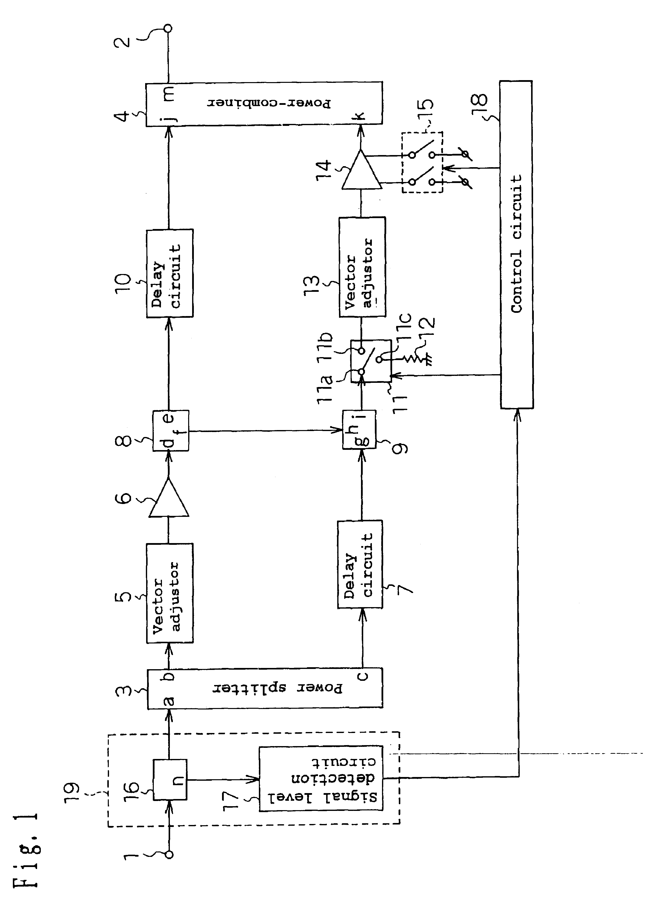
FIG. 1 shows a configuration diagram of the feedforward amplifier according to the embodiment 1 of the invention. In FIG. 1, reference numeral 11 denotes a switch circuit, 12 a terminating resistor, 15 an error amplifier power switch, 16 a power splitter, 17 a signal level detection circuit, and 18 a control circuit for switching the switch circuit 11 and the error amplifier power switch circuit 15 depending on the signal level detected by the signal level detection circuit 17, respectively. The power splitter 16 and the signal level detection circuit 17 constitute a signal level detection portion 19. Further, a symbol n added to the power splitter 16 shows a port.
By the way, the power splitter 3 of the present embodiment is an example of the first power splitter of the invention, the vector adjustor 5 an example of the first vector adjustor, the power splitter 8 an example of the second power splitter, the delay circuit 7 an example of the first delay circuit, the pow...
embodiment 2
The embodiment 2 according to of the invention provides a feedforward amplifier in which, when an abnormal event occurs in the main amplifier 6; the error amplifier 14 directly amplifies input signals for outputting. When the main amplifier 6 normally operates, a difference between the output signal level detected by the signal level detection portion 29 and the input signal level detected by the signal level detection portion 19 (the gain of the feedforward amplifier) is kept constant. However, the signal level difference between the output signal and the input signal is out of the constant value, the main amplifier is then judged to be abnormal.
When the main amplifier 6 operates normally, the control circuit 18 directly connects a common terminal 21a to an output switching terminal 21b of the switch circuit 21 and also turns on the main amplifier power-switch-circuit 23. At this time, the feedforward amplifier according to the embodiment 2 of the invention performs the same operat...
embodiment 3
The embodiment 3 according to invention provides the feedforward amplifier in which, when the output power reduces considerably lower than the nominal output power, the error amplifier 14 directly amplifies input signals for outputting. When an input signal level detected by the signal level detection circuit 17 is not lower than P2 (dBm), the control circuit 18 connects the common terminal 21a to the output switching terminal 21b of the switch circuit 21 and further turns on the main amplifier power-switch-circuit 23. At this time, the feedforward amplifier according to the invention performs the same operation as conventional feedforward amplifiers.
On the other hand, when the input signal level is not higher than P2 (dBm), the control circuit 18 connects the common terminal 21a to the output switching terminal 21c of the switch circuit 21 and turns off the main amplifier power-switch-circuit 23, and further changes the variable power-combiner 20 from a loose coupling state (e.g. 1...
PUM
 Abstract
Description
Claims
Application Information