Wind powered hydroelectric power plant and method of operation thereof

a hydroelectric power plant and wind power technology, applied in the direction of fluid couplings, servomotors, sustainable manufacturing/processing, etc., can solve the problems of windmills connected to electrical generators that cannot consistently produce 60 cycle electricity, batteries must be replaced at great expense, and battery packs run out of electrical power too quickly

Inactive Publication Date: 2004-04-13
NEW WORLD GENERATION
View PDF8 Cites 100 Cited by
  • Summary
  • Abstract
  • Description
  • Claims
  • Application Information

AI Technical Summary

Problems solved by technology

When the wind stops blowing the battery packs run out of electrical power too quickly.
Also, when the batteries in the battery pack have been charged and discharged a number of times, the batteries must be replaced at great expense.
Windmills connected to electrical generators cannot consistently produce 60 cycle electricity because of the variation in the speed of the windmills.
Without 60 cycle electricity, previous windmill / electricity systems cannot be connected into a grid system of an electrical utility.
Current windmill systems that generate electricity through an electrical generator have a disadvantage in that no electricity is generated by the windmills when the wind is not blowing.
Further, existing windmill systems do not store sufficient energy created when the wind is blowing where that energy can be used to generate electricity when the wind is not blowing.
Still further, battery packs can be very expensive and they do not store energy for a sufficiently long time.
Also, battery packs can lose their capacity for recharging and then must be replaced.

Method used


Image

  • Wind powered hydroelectric power plant and method of operation thereof
  • Wind powered hydroelectric power plant and method of operation thereof
  • Wind powered hydroelectric power plant and method of operation thereof

Examples


Embodiment Construction

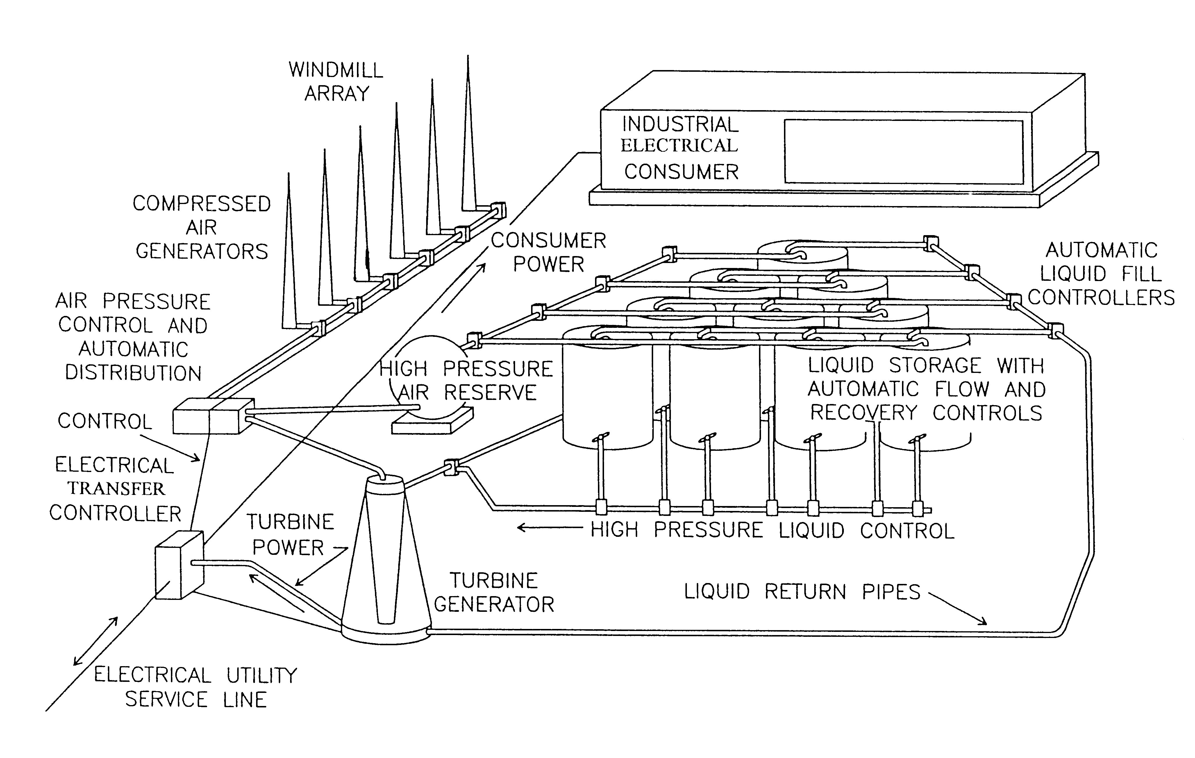
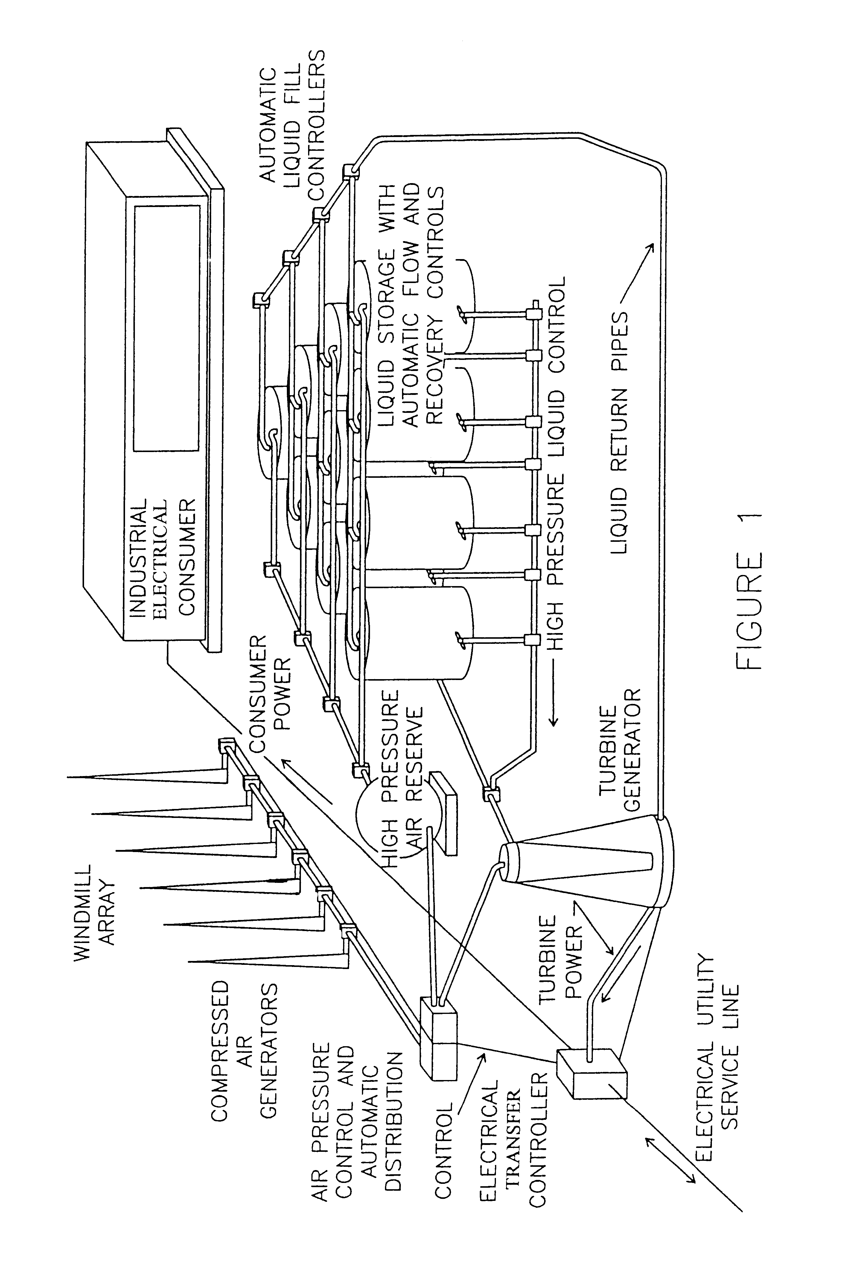
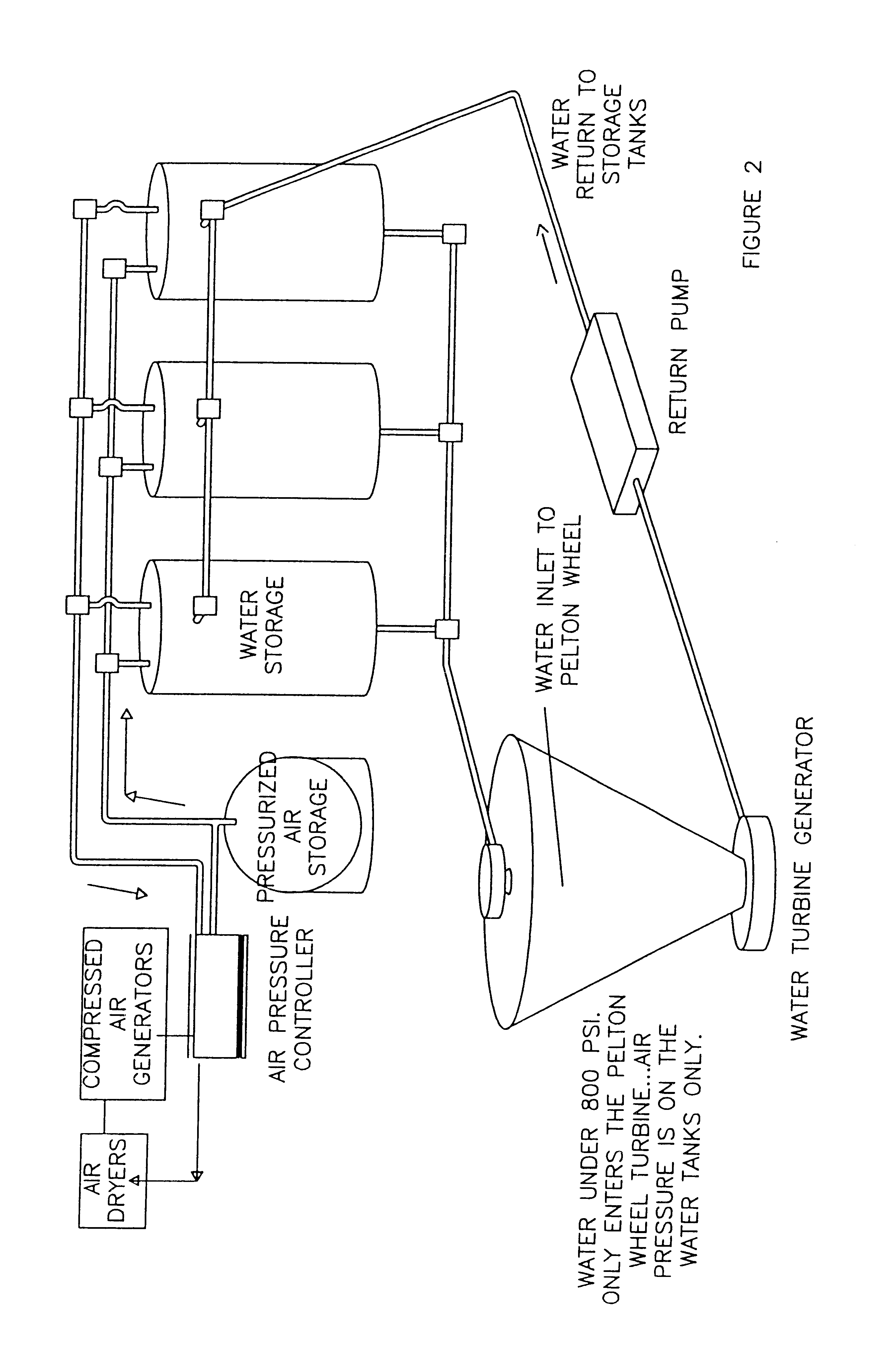
In FIG. 1, there is shown a windmill array representing a plurality of windmills. The windmills ate each connected to a compressed air generator. The compressed air generators are connected to an air pressure control and automatic distribution device that transfers pressurized air to a high pressure air reserve system or directly to a plurality of liquid storage tanks that are substantially filled with water (except in very cold weather climates where anti-freeze must be added to the water to ensure that it does not freeze). The high pressure air reserve system is a series of air storage tanks. Each of the compressed air generators has an air dryer to dry the compressed air produced by the air generator. Other air dryers are located in the hydroelectric power plant as required. After the water has been placed in the liquid storage tanks, high pressure air is introduced into the top of the liquid storage tanks either from the high pressure air reserve system or directly from the air ...


PUM


Abstract

A hydroelectric power plant uses a plurality of windmills connected to compressed air generators to produce pressurized air. Pressurized air is used to drive water through a turbine to produce electrical power. The water is recycled and the power plant includes reserve pressurized air tanks to allow the plant to continue to operate when the wind levels are not sufficient to produce high pressure air. The power plant is designed to be operated on a continuous basis based on wind power. When the wind subsides and the reserve capacity has been exhausted, electricity can be drawn from the local utility supplier. When excess power is generated by the power plant, electricity from the power plant can be added to the grid of the local electricity supplier.

Description

1. Field of the InventionThis invention relates to a wind powered hydro electric power plant and a method of operation thereof More particularly, this invention relates to a hydroelectric power plant where water is forced through a turbine by high pressure air produced by wind energy and a method of operation thereof.2. Description of the Prior ArtIt is known to have windmills connected to compressed air generators to produce pressurized air. It is also known to have windmills that are used to produce electricity with battery packs as back up to produce electricity when the wind is not blowing. The battery packs are charged by the electrical generators connected to the windmills. When the wind stops blowing the battery packs run out of electrical power too quickly. Also, when the batteries in the battery pack have been charged and discharged a number of times, the batteries must be replaced at great expense. Windmills can generate electricity simply by having an electrical generator...

Claims


Application Information

Patent Timeline
Patent Type & Authority Patents(United States)
IPC IPC(8): F03B1/00F03B1/02F03D9/00F03D9/02F03B13/00F03B13/06F03D1/02
CPCF03D9/001F03D9/008F03D9/02F03D9/028Y02E10/725Y02E60/15Y02E60/17F03D9/10F03D9/17F03B13/06F03D9/28Y02P90/50F03D9/25F03D1/02Y02E10/20Y02E10/72Y02E60/16Y02P80/10
Inventor MERSWOLKE, PAUL H. F.GARDNER, THOMAS B.
Owner NEW WORLD GENERATION
Why Eureka
Try Eureka