
Single sweep phase shift method and apparatus for measuring chromatic and polarization dependent dispersion

a phase shift and phase shift technology, applied in the field of optical measurement, can solve the problems of limiting the information carrying capacity pulse distortion, otherwise affecting the quality of an optical signal transmitted through the system,

Inactive Publication Date: 2004-04-20
AGILENT TECH INC
View PDF10 Cites 5 Cited by
  • Summary
  • Abstract
  • Description
  • Claims
  • Application Information

AI Technical Summary

Benefits of technology

The present invention provides a technique for accurately determining chromatic and polarization dependent dispersion, as well as other optical properties of an optical device. This is important for designers and manufacturers of optical communication systems, as chromatic dispersion negatively impacts the quality of optical signals transmitted through the system. The technique allows for a relaxation of wavelength repeatability requirements of the optical source and reduces the measurement time required. The invention also provides apparatus for accurately measuring chromatic dispersion and other optical properties of an optical device.

Problems solved by technology

Chromatic dispersion of an optical communications system can significantly limit the information carrying capacity of an optical signal transmitted through the system.
Particularly in an optical communications system that operates at a high bit rate, e. g., 40 Gbps or more, chromatic dispersion can result in pulse distortion and otherwise affect the quality of an optical signal transmitted through the system.
Polarization dependent dispersion, also referred to as polarization-mode dispersion or PMD, can also limit the information carrying capacity of an optical signal in an optical communications system by limiting the bit rates that are achievable in the system.

Method used


Image

  • Single sweep phase shift method and apparatus for measuring chromatic and polarization dependent dispersion
  • Single sweep phase shift method and apparatus for measuring chromatic and polarization dependent dispersion
  • Single sweep phase shift method and apparatus for measuring chromatic and polarization dependent dispersion

Examples


Embodiment Construction

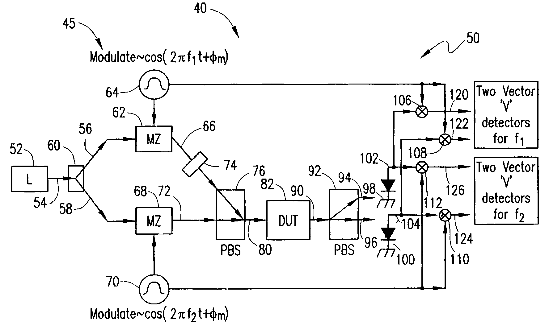
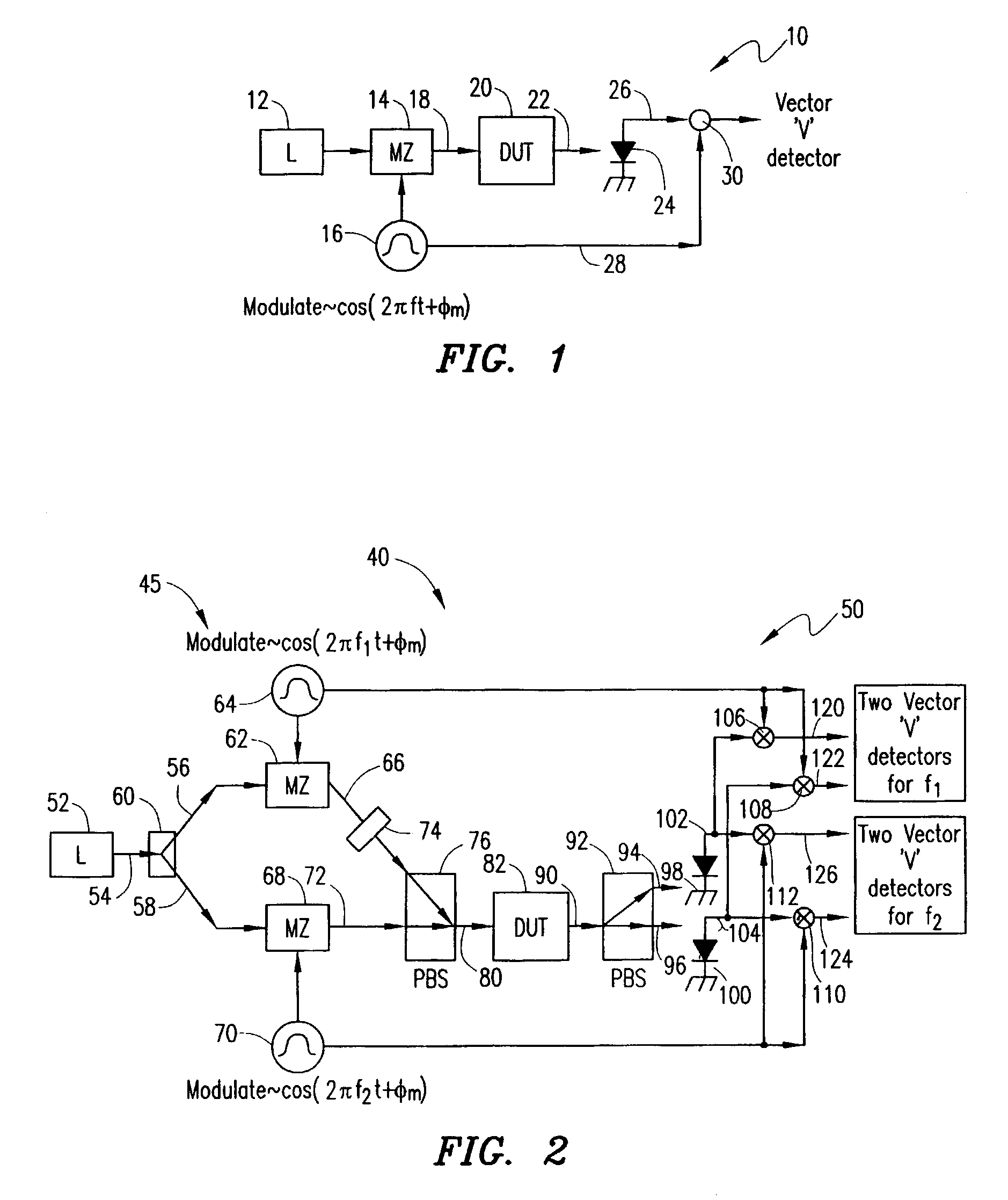
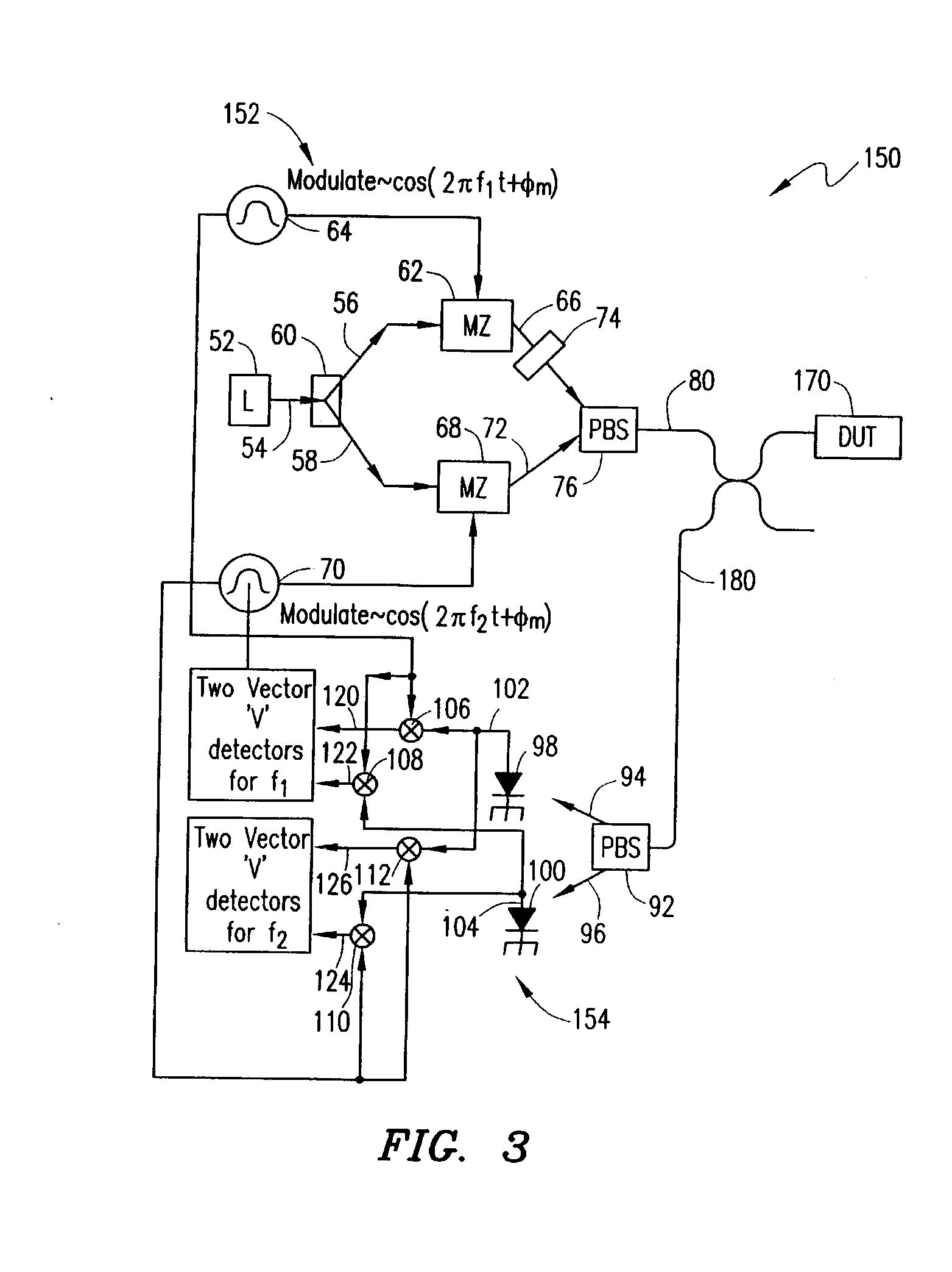
Embodiments in accordance with the invention provide a technique for accurately determining chromatic dispersion, polarization dependent dispersion and other optical properties of an optical device. The technique permits a relaxation of wavelength repeatability requirements of an optical source used in the technique and may be completed in a reduced period of time.

Because chromatic dispersion negatively influences the quality of an optical signal carried by an optical communications system, it is important for a designer or a manufacturer of an optical communications system to precisely control the chromatic dispersion of the system. A typical optical communications system is composed of a plurality of separate optical devices, for example, a plurality of spans of optical fiber, and each device may have a different chromatic dispersion. In order to minimize the total chromatic dispersion of the system, it is necessary to compensate for the chromatic dispersion introduced by each dev...


PUM

PropertyMeasurementUnit
optical propertyaaaaaaaaaa
frequenciesaaaaaaaaaa
opticalaaaaaaaaaa

Abstract

A method for determining at least one optical property of an optical device comprises providing an optical input signal that includes first and second signal components that are modulated at first and second frequencies, respectively, and that have first and second polarization states, respectively. The optical input signal is passed to an optical device. An optical output signal from the optical device is separated into first and second output signals that have third and fourth polarization states, respectively. The first and second output signals are each compared with reference signals at the first and second frequencies to provide four phase shift and amplitude measurements that can be used to determine the at least one optical property of the optical device as a function of wavelength.

Description

1. Technical Field of the InventionThe present invention relates generally to the optical measurement field More particularly, the invention relates to a method and apparatus for determining chromatic and polarization dependent dispersion and other optical properties of an optical device.2. Description of Related ArtChromatic dispersion of an optical communications system can significantly limit the information carrying capacity of an optical signal transmitted through the system. Particularly in an optical communications system that operates at a high bit rate, e. g., 40 Gbps or more, chromatic dispersion can result in pulse distortion and otherwise affect the quality of an optical signal transmitted through the system.Polarization dependent dispersion, also referred to as polarization-mode dispersion or PMD, can also limit the information carrying capacity of an optical signal in an optical communications system by limiting the bit rates that are achievable in the system. PMD aris...

Claims


Application Information

Patent Timeline
Patent Type & Authority Patents(United States)
IPC IPC(8): G01M11/00
CPCG01M11/3181G01M11/336
Inventor MCALEXANDER, WILLIAM IANVANWIGGEREN, GREGORY DOUGLAS
Owner AGILENT TECH INC
Learn More