High performance flush valve assembly

a flush valve and high-performance technology, applied in water installations, flushing devices, construction, etc., can solve the problems of not enhancing the hydraulic energy available, difficult to achieve superior flush performance,

Inactive Publication Date: 2004-05-04
AS IP HOLDCO LLC
View PDF6 Cites 36 Cited by
  • Summary
  • Abstract
  • Description
  • Claims
  • Application Information

AI Technical Summary

Benefits of technology

It is also an advantage of the present invention to provide a flush valve assembly which has a greater energy throughput of the flush water in comparison to existing flush valve assemblies to thereby provide more available energy to remove waste from the toilet bowl.
By including the "trip release" or "lost motion" mechanism in the present invention, the flow characteristics of a flush valve assembly are not only improved but also the flush valve assembly complies with mandated agency requirements.

Problems solved by technology

In the past, toilet designs have attempted by various methods to comply with this reduced water requirement, but achieving superior flush performance has been difficult.
However, the hydraulic energy available is not enhanced by the typical flush valve design for a coaxial flush valve assembly wherein the effective flow diameter through the flush valve opening is less than the orifice diameter of the flush valve inlet under dynamic conditions.

Method used


Image

  • High performance flush valve assembly
  • High performance flush valve assembly
  • High performance flush valve assembly

Examples


Embodiment Construction

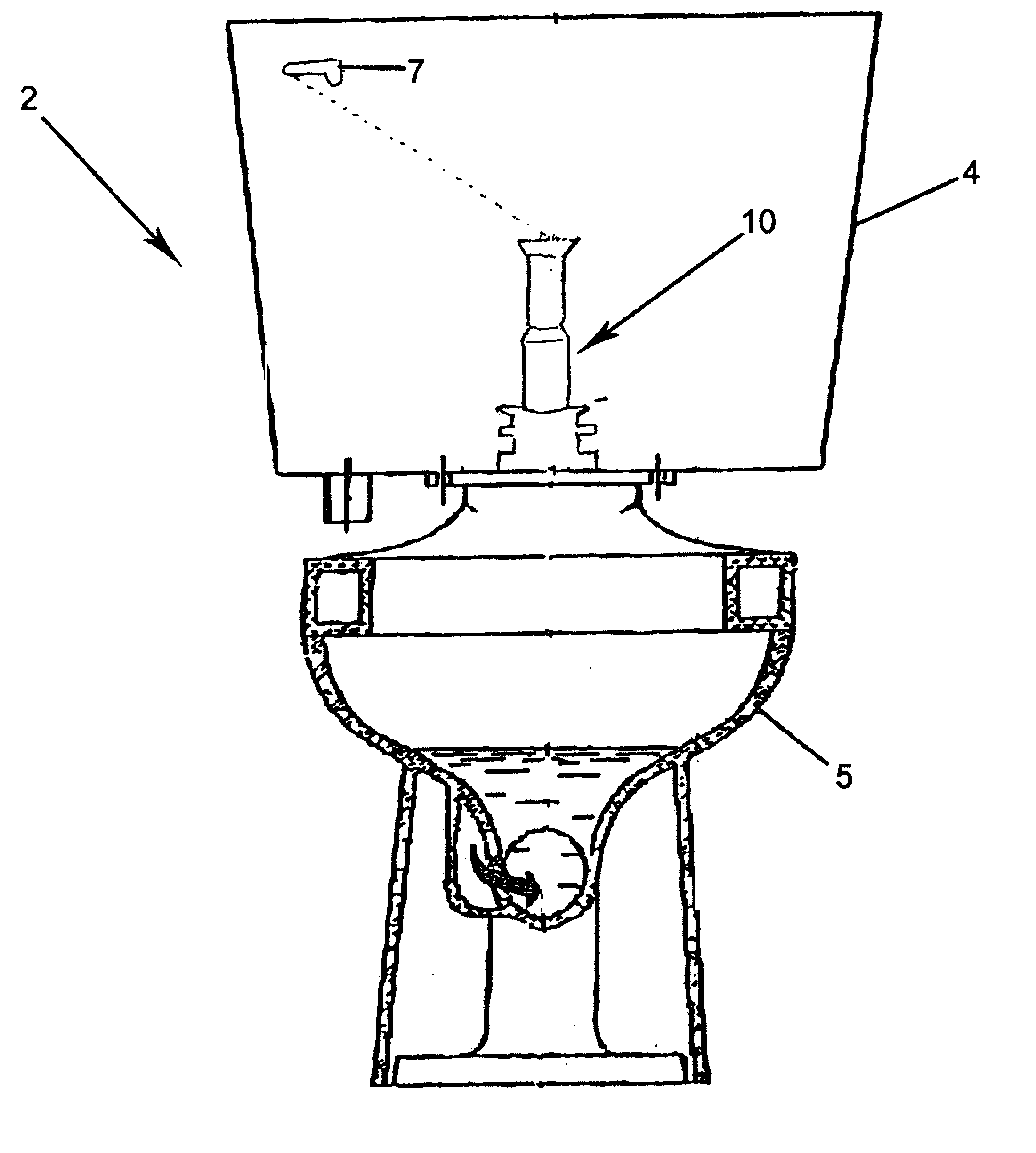
A flush valve assembly 10 in accordance with the teachings of the present invention is illustrated in FIG. 1 incorporated in a toilet assembly 2. As will be explained in more detail below, this flush valve assembly 10, which is provided in a water tank 4, has a greater energy throughput of the flush water in comparison to existing flush valve assemblies to thereby provide more energy available to remove waste from a toilet bowl, such as 5. In addition, this flush valve assembly permits a water closet to meet governmental agency requirements which mandate a minimum "hold-down" duration of the flush activation member or flush lever of 1 second and a maximum water usage of 1.6 gallons (6 liters) per flush. Further, this flush valve assembly improves the flow characteristics of the flush water and flow capacity of the flush valve assembly.

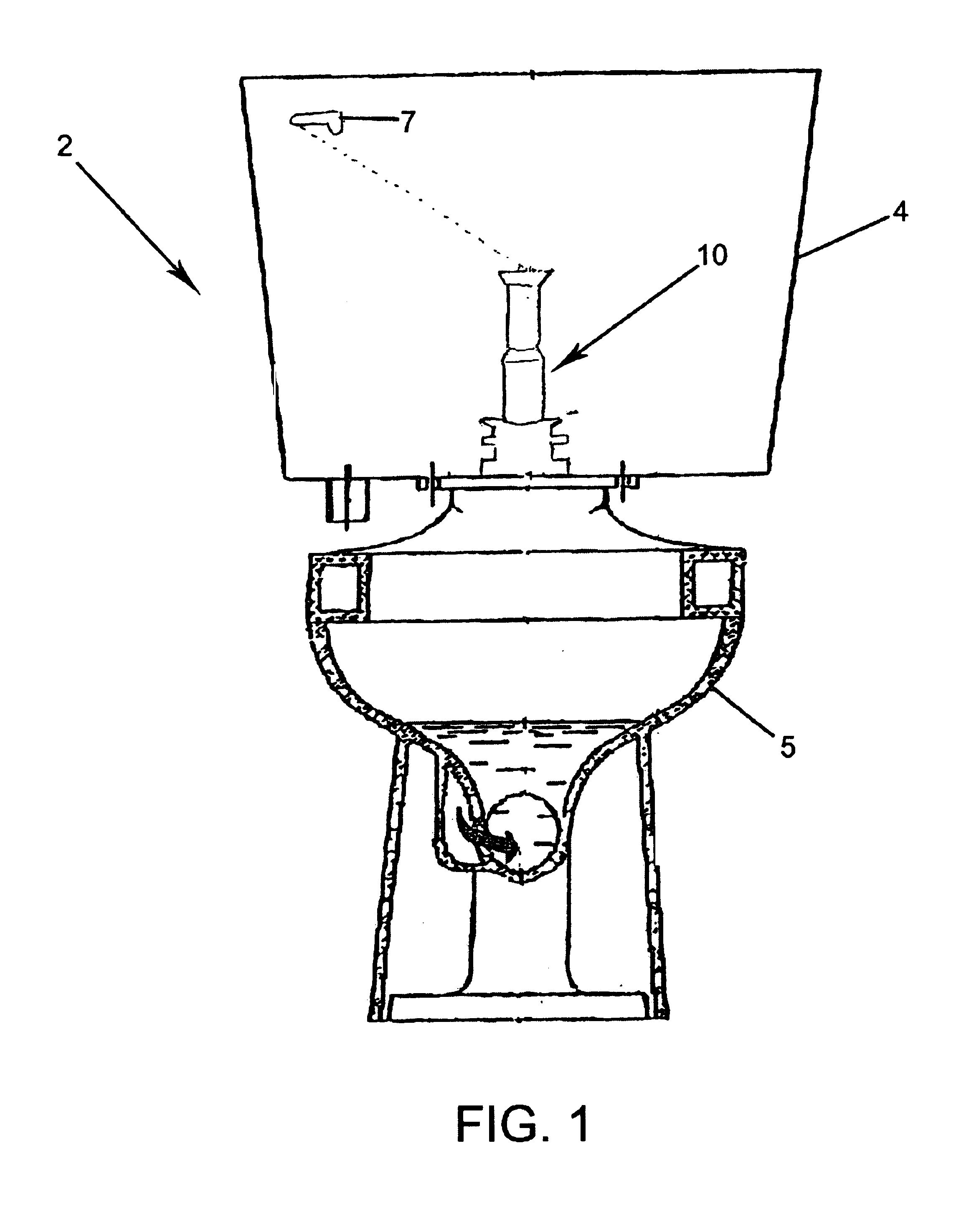
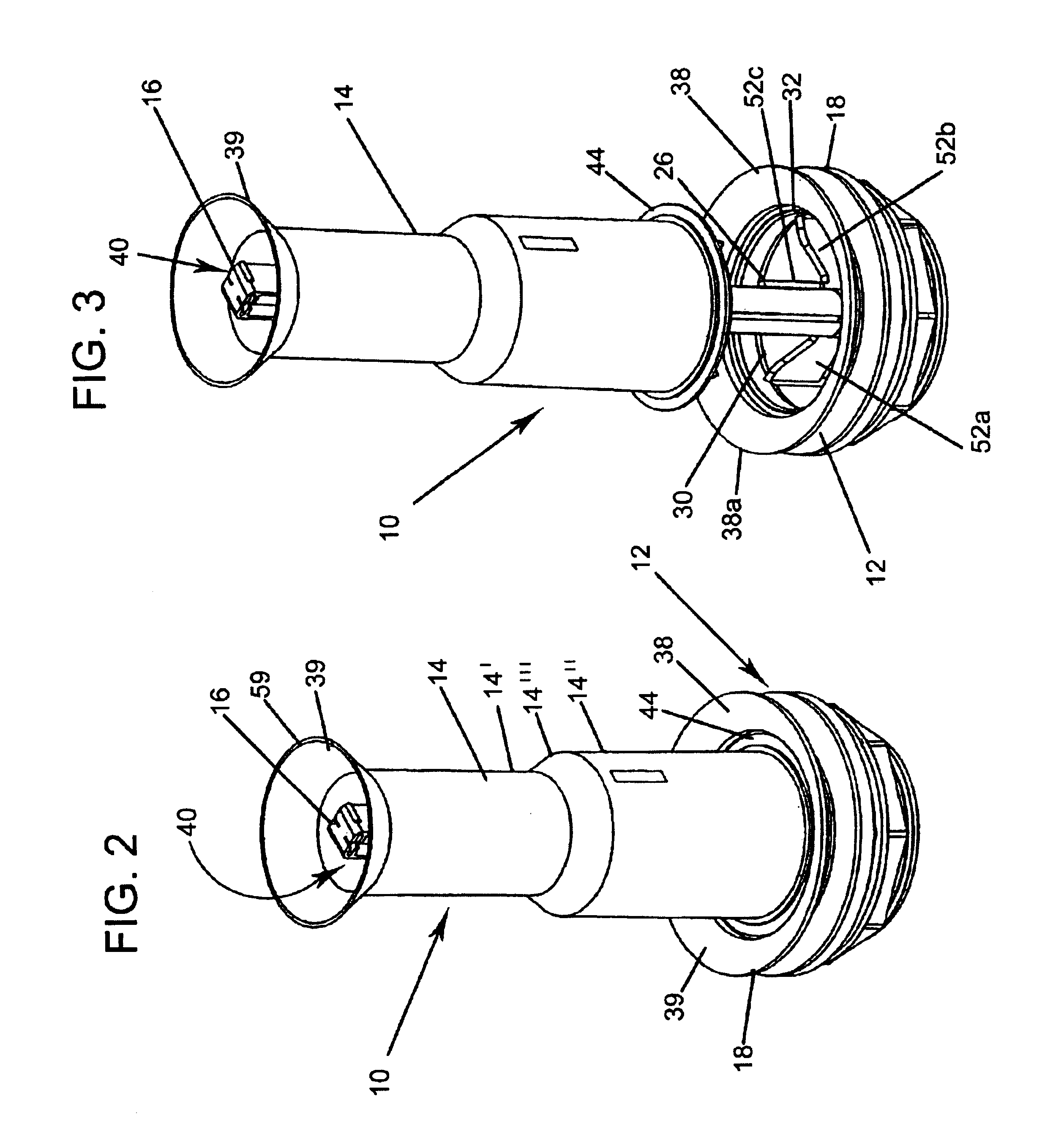
As is shown in FIGS. 2 through 4, the flush valve assembly 10 of the present invention includes a valve body 12, a flush cover member 14 of a predeter...


PUM


Abstract

A flush valve assembly for a water tank of a water closet which includes a first valve member which can be secured to the water tank and has a base sleeve position including a radiused inlet to thereby increase the discharge coefficient of the valve opening. A second valve member is coaxially and slidably mounted with respect to the first valve member so that the valve opening is created between the first and second valve members when the second valve member is removed from the first valve member. The second valve member is slidably movable between a first rest position, wherein the second valve member is seated on the base sleeve portion of the first valve member so that water cannot pass through the valve opening, and a second position, wherein the second valve member is removed from the base sleeve portion of the first valve member so that water can pass through the valve opening. A sealing member is provided for sealing the valve opening when the second valve member is in its first rest position and seated on the base sleeve portion of the first valve member. A guiding assembly is further provided for properly guiding and aligning the second valve member with respect to the first valve member when the second valve member is moved between its first and second position. The flush valve assembly also includes a trip release mechanism is further provided for releasing the effect of the flush lever on the second valve member when the second valve member reaches its second position so as to return the second valve member to its first rest position prior to the flush lever returning to its first rest position.

Description

The present invention relates to a flush valve assembly for use in a water tank of a water closet. More particularly, the present invention relates to a flush valve assembly which has a coaxial design which provides for greater energy throughput thereby causing more energy to be available to remove wastes from the toilet bowl. The greater throughput is achieved by using a greater orifice diameter and including a radius on the inlet side of the valve opening. In addition, the present invention relates in particular to a flush valve assembly having a "trip release" or "lost motion" mechanism to effectively disengage the valve opening / closing member from the flush activation member or flush lever.Toilets for removing waste products are well known. Typically, toilets incorporate three systems that work together to perform the flushing action. Those systems are (1) the bowl siphon, (2) the flush mechanism, and (3) the refill mechanism. Working in concert, these three systems allow the fl...

Claims


Application Information

Patent Timeline
Patent Type & Authority Patents(United States)
IPC IPC(8): E03D1/34E03D1/30
CPCE03D1/34
Inventor HAN, JOSEPH UNKYUNG
Owner AS IP HOLDCO LLC
Why Eureka
Try Eureka