

Method of desalination and wastewater treatment in a microbial desalination cell reactor
a desalination cell and desalination technology, which is applied in the direction of water/sludge/sewage treatment, water treatment compounds, specific water treatment objectives, etc., can solve the problems of energy-consuming and labor-intensive desalination process of brackish/saline water, and achieve significant reduction of fouling, improve initial performance, and reduce the salinity of saline solution
- Summary
- Abstract
- Description
- Claims
- Application Information
AI Technical Summary
Benefits of technology
Problems solved by technology
Method used
Image

Examples
example 1
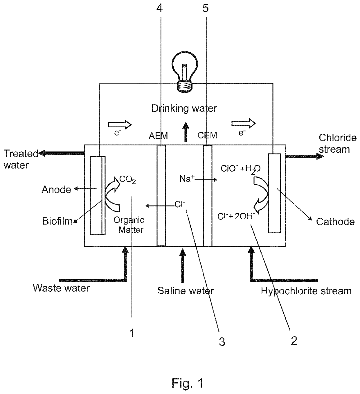
Simultaneous Oxidation of Organic Matter, Saline Water Desalination and Electric Power Generation in a Microbial Desalination Cell.
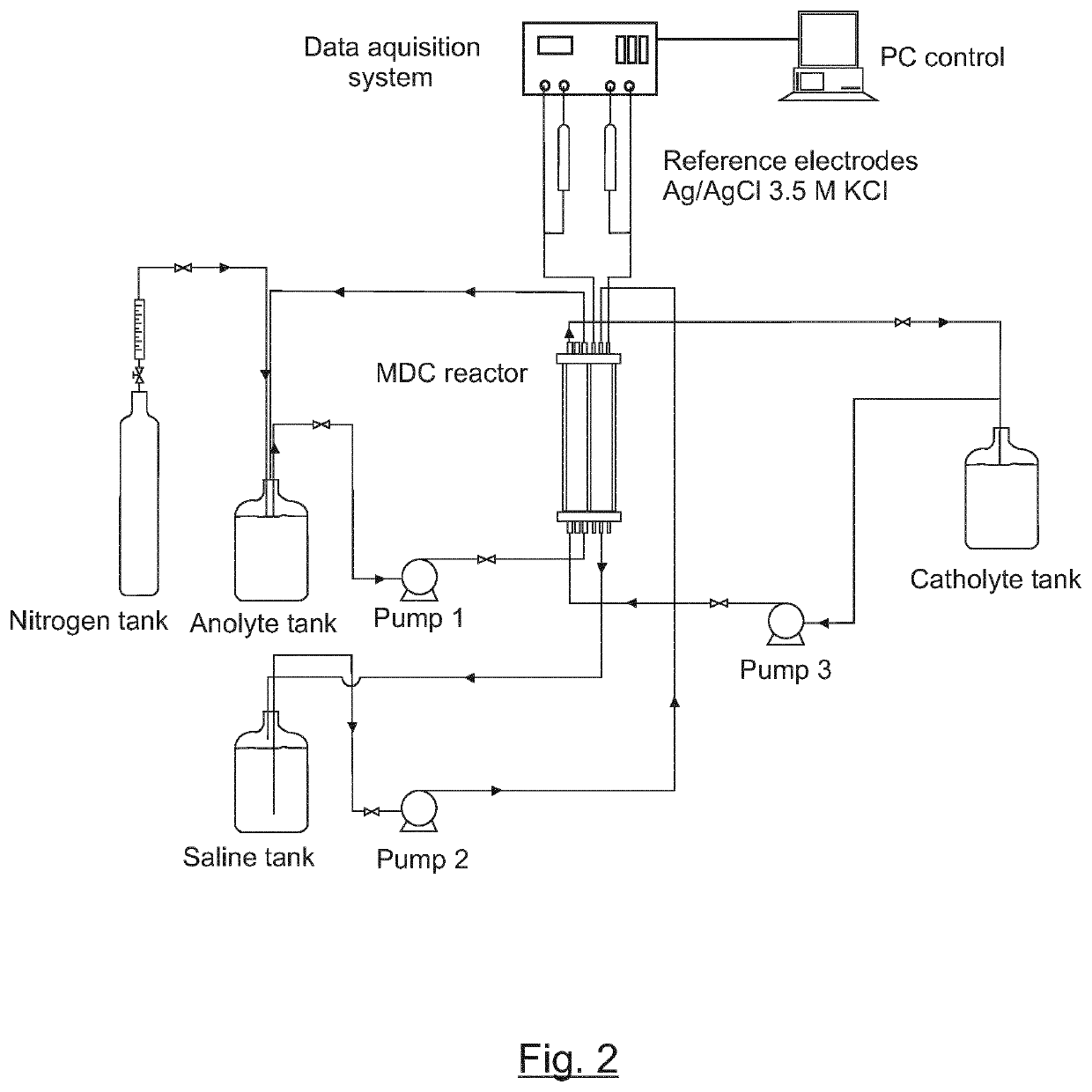
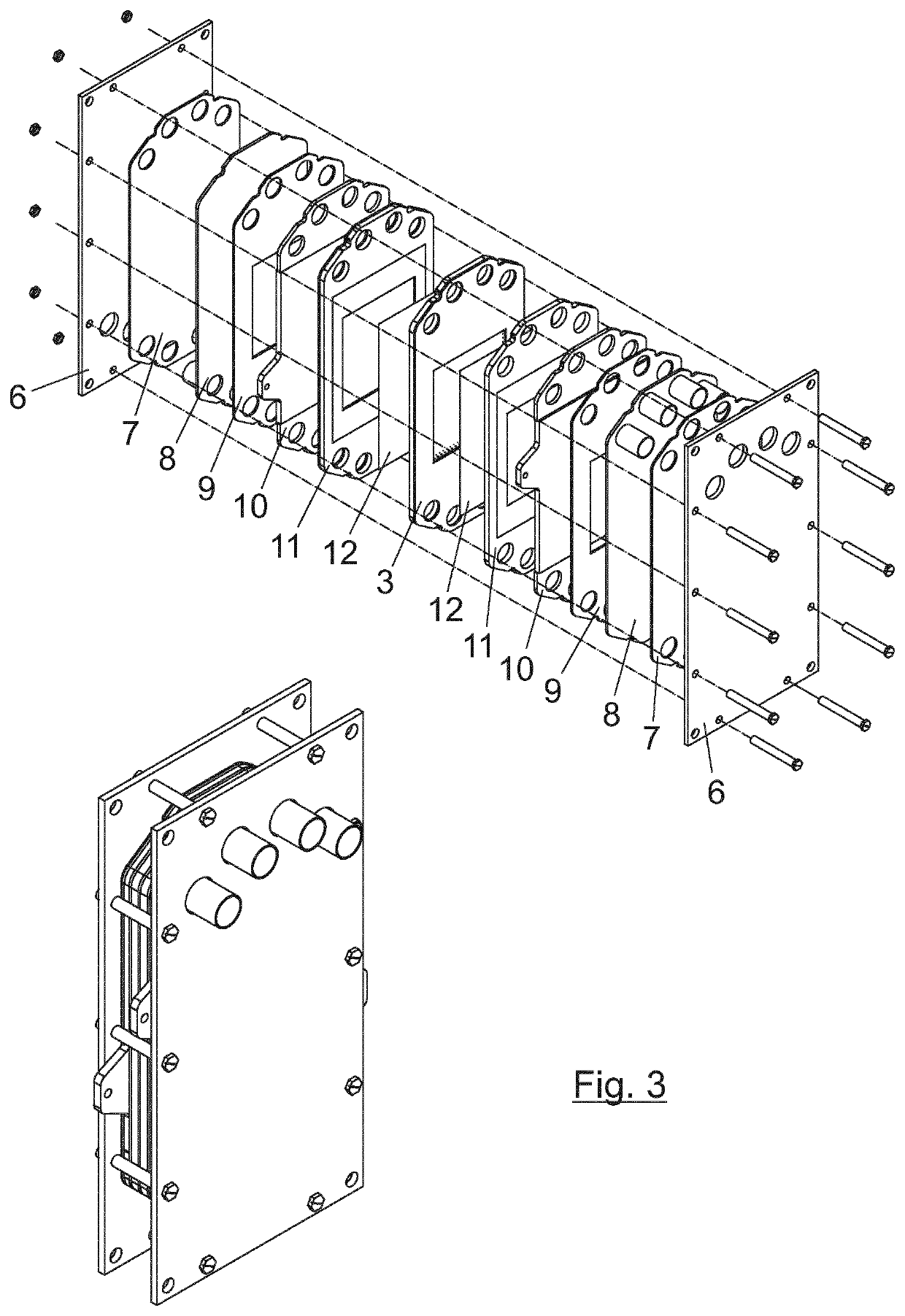
[0042]Stage 1: The MDC reactor is a three chamber electrochemical reactor with a collector area of 100 cm2 and a compartment length of 12 mm (E-Cell). The anodic chamber is filled with carbon felt RVC 4000 (Mersen Ltd) and a graphite plate was used as electric current collector. Conducting paste was used to glue the carbon felt to the collector. A graphite plate was used as cathode, and a turbulence promoter was located inside the cathodic chamber.
[0043]Electrodialysis conventional membranes, AMX (anionic) and CMX (cationic) (Astom Corporation) were used as ion exchange membranes. Two reference electrodes (Ag / AgCl 3.5 M) were placed in the geometric centre of both anodic and cathodic compartments in order to measure anodic and cathodic potentials.
[0044]G. sulfurreducens is cultured in batch using a fresh water medium (FWM) containing: 10 mM Acetate / 40 mM...
example 2
Experiments of Simultaneous Oxidation of Organic Matter, Saline Water Desalination and Electric Power Generation in a Microbial Desalination Cell
[0048]Six experiments according to the process of the invention were carried out in the operation conditions disclosed in Table 1. The results are also shown in FIG. 4.
[0049]
TABLE 1Results: final conductivity 0.5 mS / cm, anolyte 20 mM Acetate + fresh water medium(FWM), catholyte NaClO (3%).Initial / DesalinationVolumeSalineFinaltime (h) / Anolyte / Catholyte / compartmentConductivityExternalEnergyWaterExperimentSaline Tankslength(mS / cmresistorproducedproductionid(L)(mm)25° C.)(Ohm)(Wh / m2)(m3 / day m2)110 / 10 / 212 8-0.50018.2-0.27210 / 10 / 26 4-0.50011.0-0.43310 / 10 / 26 8-0.50017.6-0.27410 / 10 / 26 4-0.5252.715.0-0.32510 / 10 / 26 8-0.52137.824.5-0.18610 / 10 / 1620-0.52213.828.3-0.08
[0050]The time-evolution of current density (A, B and C) and saline tanks conductivity (D, E and F) is shown in FIG. 4.
[0051]The Project leading to this application has received funding fro...
PUM
| Property | Measurement | Unit |
|---|---|---|
| catholyte conductivity | aaaaa | aaaaa |
| catholyte conductivity | aaaaa | aaaaa |
| Flow rate | aaaaa | aaaaa |
Abstract
Description
Claims
Application Information