Wrench rack

a technology for wrench racks and racks, applied in the field of wrench racks, can solve problems such as the complicated structure of the combinative wrench racks

Inactive Publication Date: 2004-07-06
LIN CLARE
View PDF11 Cites 71 Cited by
  • Summary
  • Abstract
  • Description
  • Claims
  • Application Information

AI Technical Summary

Benefits of technology

It is an objective of the present invention to provide a robust wrench rack.
It is another objective of the present invention to provide a simple wrench rack.
The first jaw includes a stop formed thereon. The stop of the first jaw may include an inclined face for smooth movement of the wrench handle past it to the position between the first jaw and the second jaws.
In a second aspect, each of the second jaws includes a stop formed thereon. The stop may include an arc-shaped face for smooth movement of the wrench handle past it to the position between the first jaw and second jaws.

Problems solved by technology

Moreover, the combinative wrench rack is complicated in structure.

Method used


Image

  • Wrench rack
  • Wrench rack
  • Wrench rack

Examples


Embodiment Construction

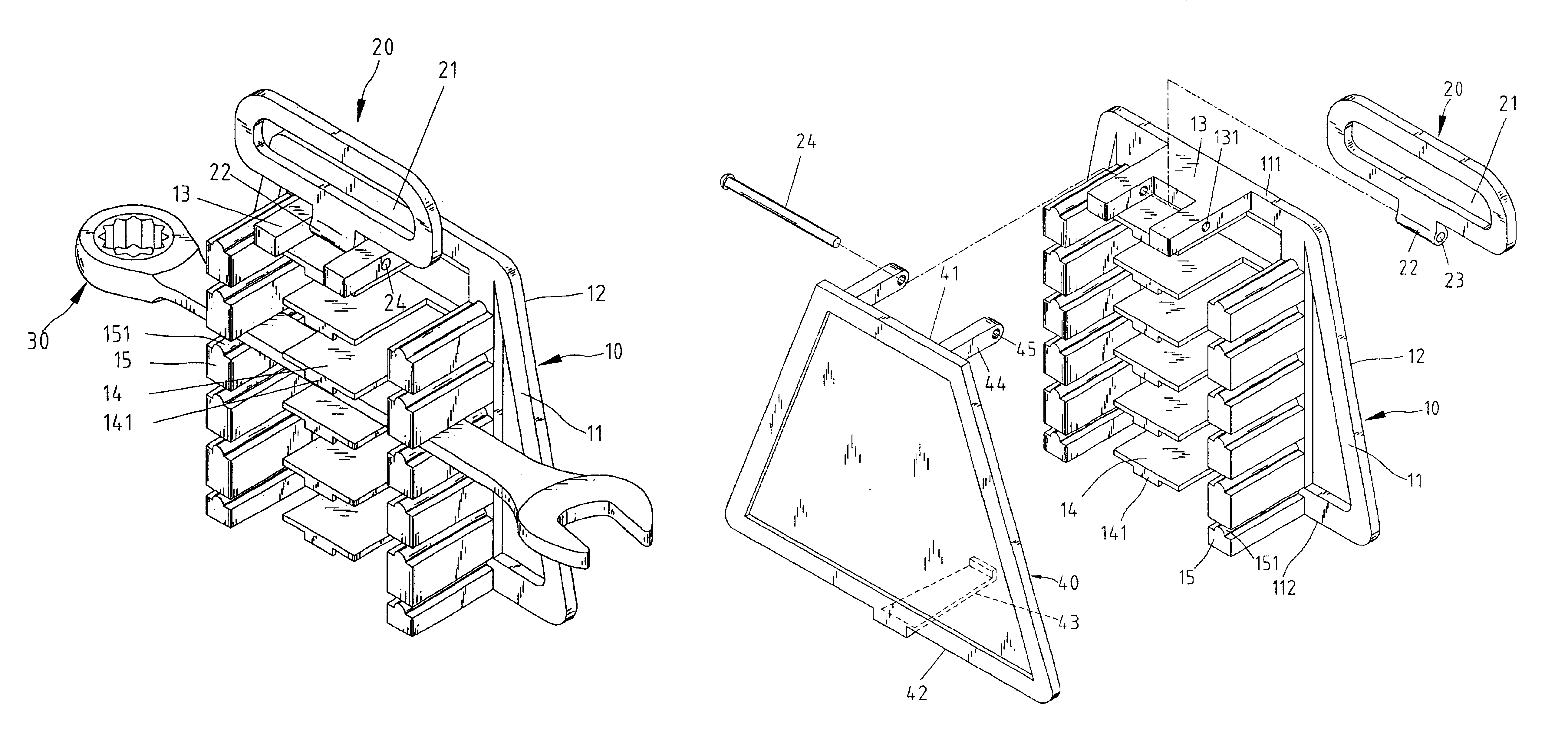
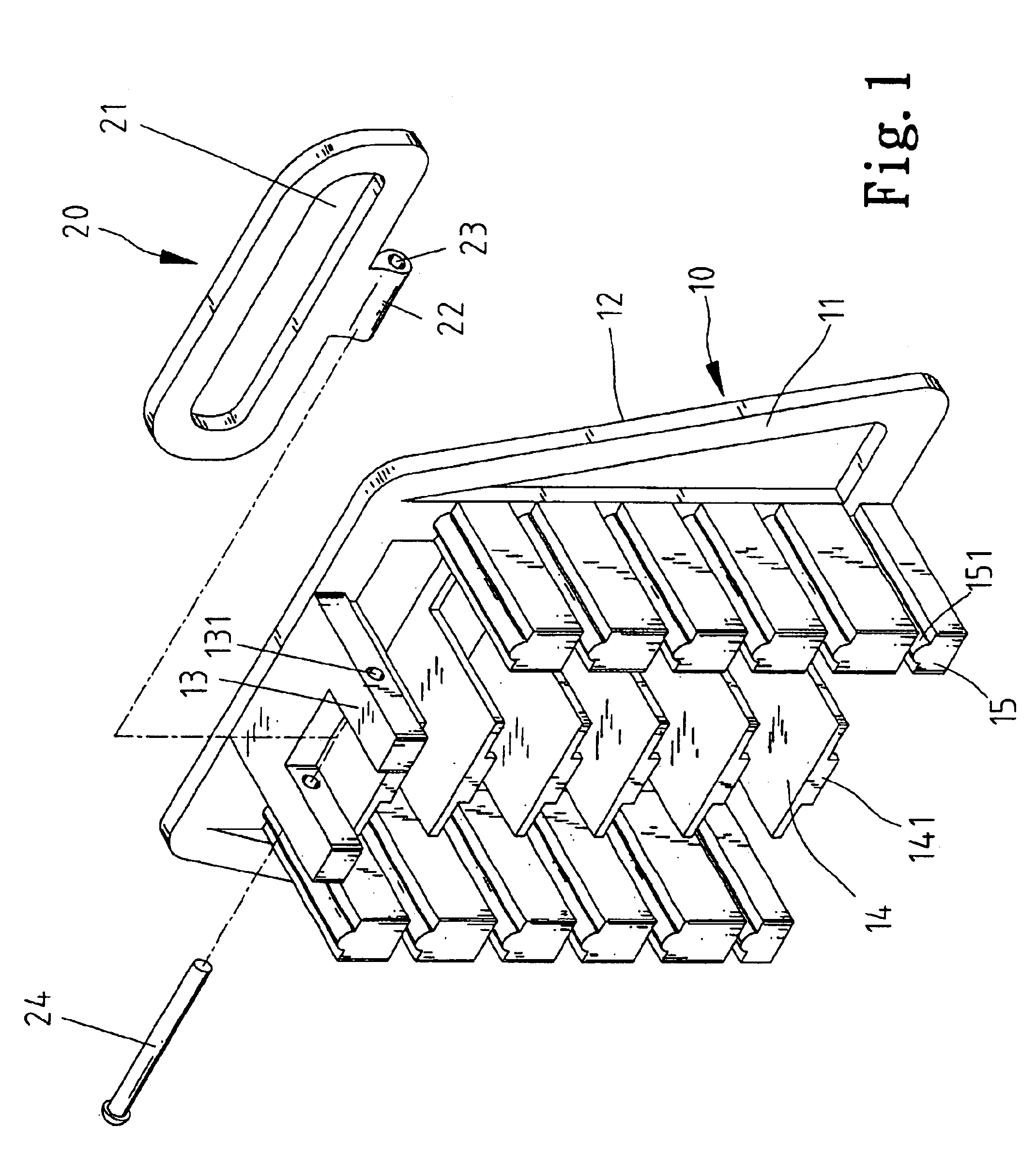
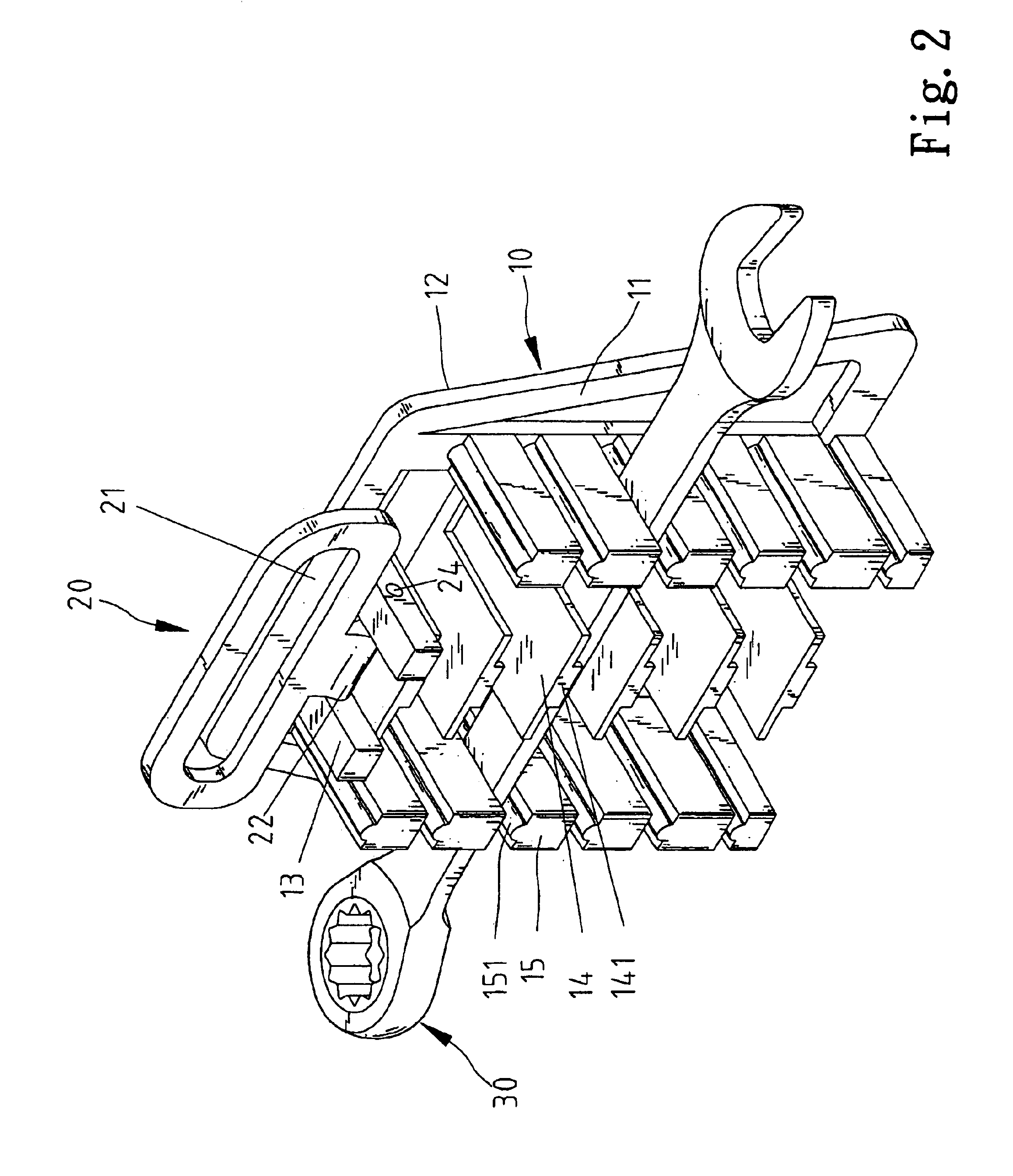
Referring to FIGS. 1 and 2, according to the preferred embodiment of the present invention, a wrench rack includes a board 10 and a handle 20 pivotally connected with the board 10. The board 10 includes a front face 11 and a rear face 12. Two separate connection portions 13 are formed on the front face 11. Each of the connection portions 13 defines an aperture 131. On an edge of the handle 20 is formed a connection portion 22 defining an aperture 23. The connection portion 22 is located between the connection portions 13 and a pin 24 is inserted in the apertures 131 and 23, thus pivotally connecting the handle 20 with the board 10. A hole 21 is defined in the handle 20 so that the handle 20 can be hung on a nail or hook mounted on a wall or the like.

A number of clips are formed on the front face of the board 10. Each of the clips includes an upper jaw 14 and two lower jaws 15. A stop 141 is formed on a lower face of the upper jaw 14. A ridge 151 is formed on an upper face of each of...


PUM


Abstract

A wrench rack includes a board and at least one clip formed on the board. The at least one clip includes a first jaw and two second jaws for retaining a wrench handle between the first jaw and the second jaws. The wrench rack may include a handle pivotally connected with the board. The wrench rack may include a cover pivotally connected with the board. The cover may include a hook formed thereon for hooking the board. The first jaw includes a hooking portion formed thereon. In a first aspect, each of the second jaws includes a ridge formed thereon. In a second aspect, each of the second jaws includes a hooking portion formed thereon.

Description

BACKGROUND OF INVENTION1. Field of InventionThe present invention relates to a wrench rack for clipping wrenches.2. Related Prior ArtTaiwan Patent Publication No. 369994 teaches a combinative wrench rack including a handle 20 and a plurality of clips 30. In the handle 20 is defined a recess 21 so that the wrench rack can be hung on a nail or hook secured to a wall or the like. On the lower edge of the handle 20 are formed a main hook 22 and two auxiliary hooks 23 so that the main hook 22 is located between the auxiliary hooks 23. On a lower edge of each of the clips 30 are formed a main hook 32 and two auxiliary hooks 33 so that the main hook 32 is located between the auxiliary hooks 33. The hook 32 is identical to the main hook 22. The auxiliary hooks 33 are identical to the auxiliary hooks 23. On an upper end of each of the clips 30 is formed an engagement plate 34 in which a main recess 35 and two auxiliary recesses 36 are defined. The main hook 22 and the auxiliary hooks 23 can ...

Claims


Application Information

Patent Timeline
Patent Type & Authority Patents(United States)
IPC IPC(8): B25H3/00B25H3/04
CPCB25H3/04
Inventor LIN, CLARE
Owner LIN CLARE
Why Eureka
Try Eureka