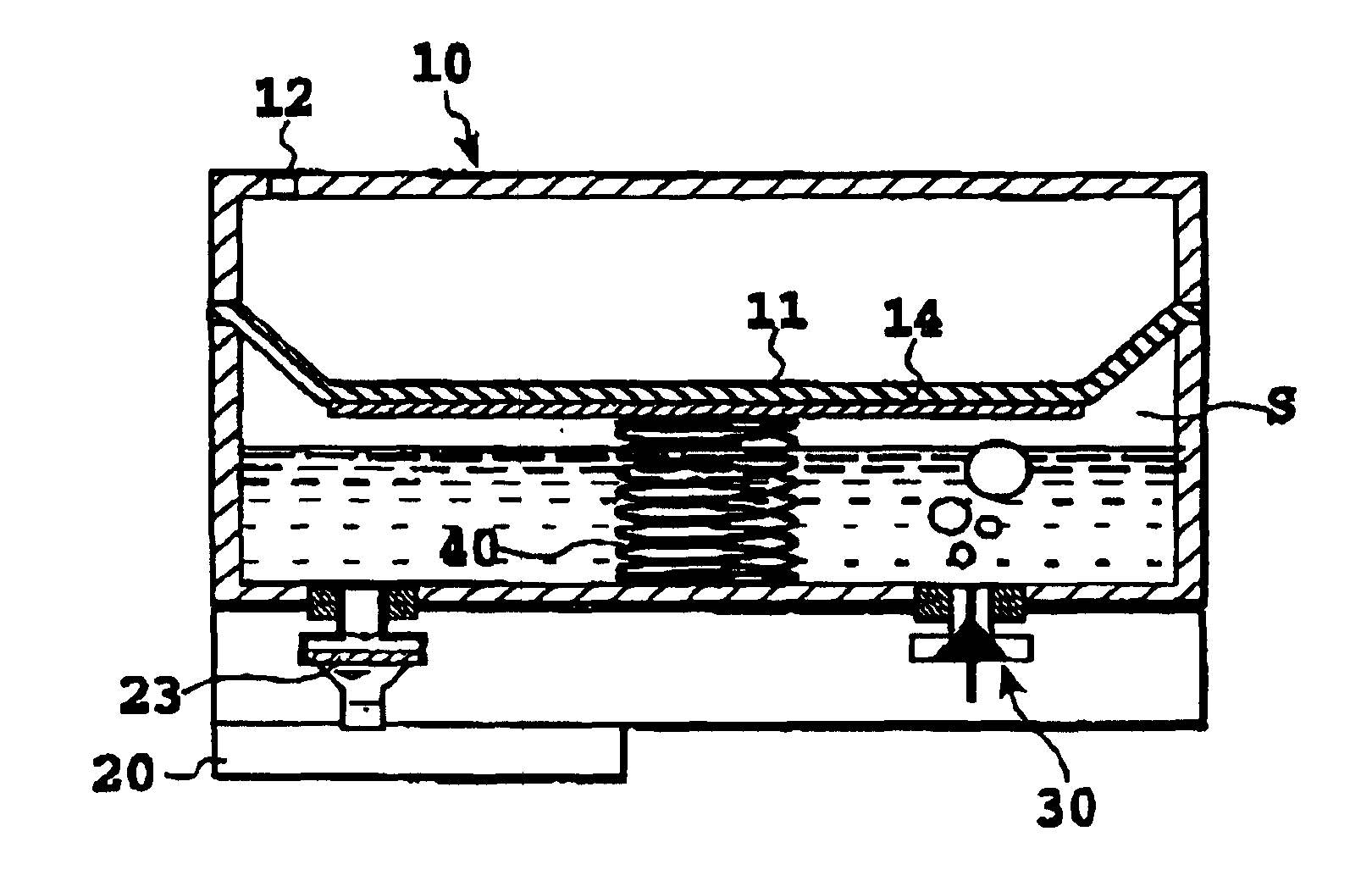
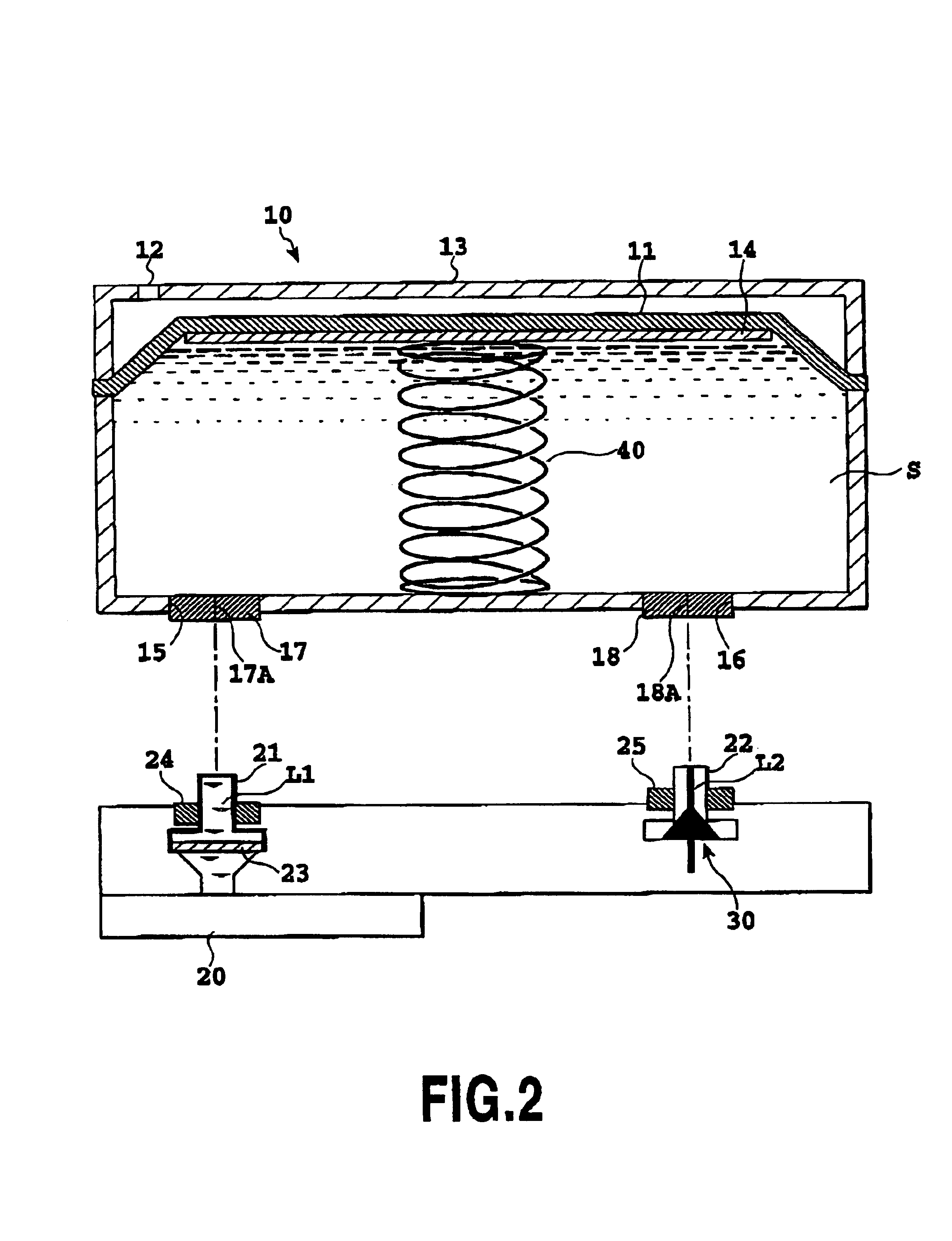
In any of the above mechanisms, however, the negative pressure tends to increase as the amount of ink in the ink tank decreases, and it becomes impossible to supply ink to a recording head stably when the level of the negative pressure exceeds a predetermined value.
This results in a problem in that the ink tank becomes unusable before the ink is completely used up.
This may result in a problem in that the negative pressure increases beyond a proper range in which an ink ejecting operation of the recording head can be performed to prevent the formation adequate meniscuses at the ink ejecting section of the recording head or in that the ink can not be satisfactorily supplied to the recording head.
This also disallows the ink to be used completely.
Some ink tanks have a configuration in which ink is contained in a bag-shaped member, and the material and shape of which are appropriately selected to generate a negative pressure by the bag-shaped member itself and which becomes flat with no space left therein when the ink is completely used up, but there are limitations on the shape of such a bag-shaped member.
Therefore, when such an ink tank is configured to be contained in a box-like housing, the configuration of the bag-shaped member does not fit the interior of the housing completely even when it is charged with ink, and the
volumetric efficiency of the ink tank is low with respect to the entire space available therein.
Such a bag-shaped member also has a problem in that its performance of supplying ink to a recording head can be reduced and in that it can make an ink ejecting operation of a recording head unstable when ink is nearly used up because of a high negative pressure.
However, those methods require a plurality of parts in a region where air is introduced, and the structure of such a region has therefore become complicated.
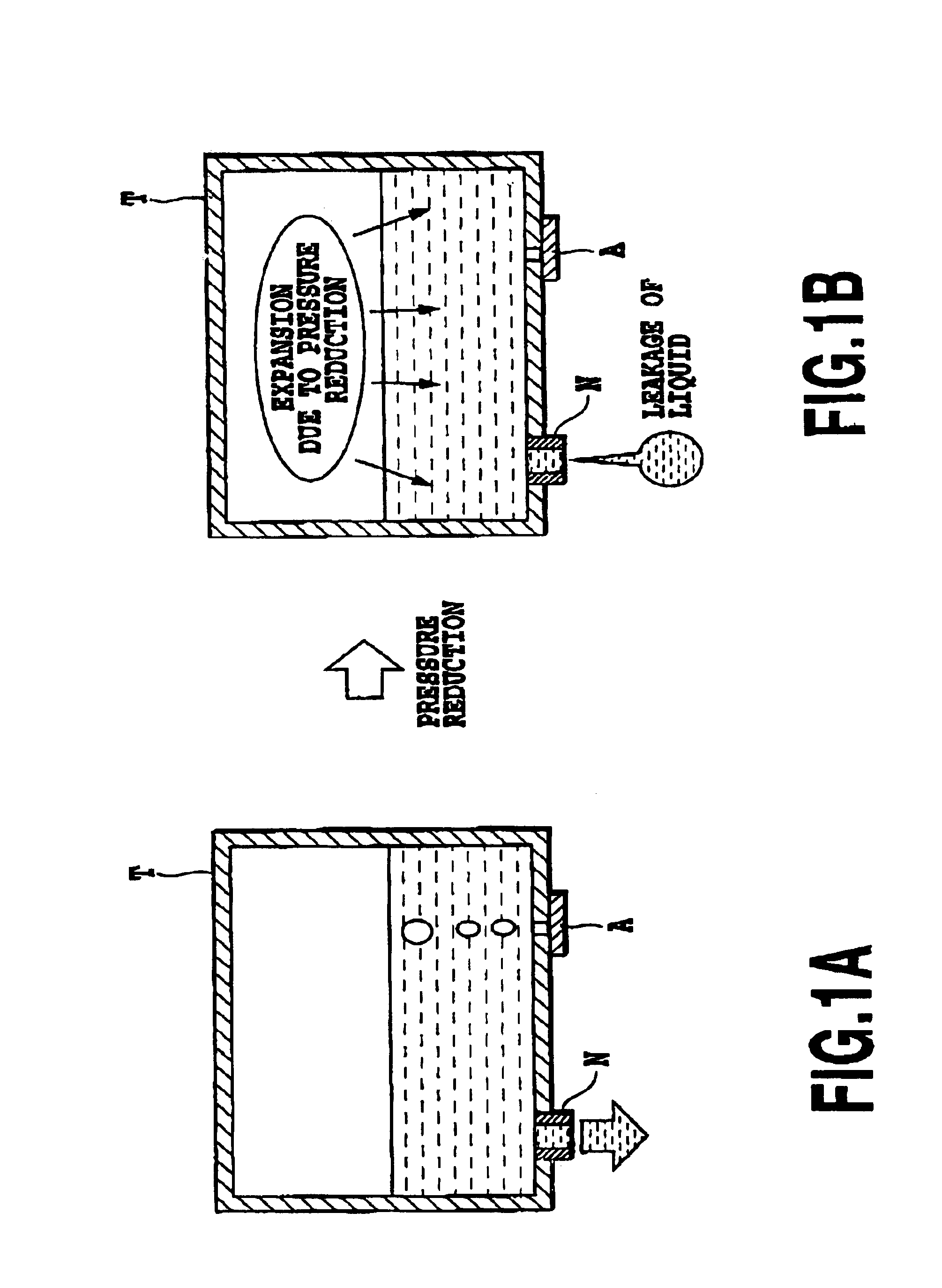
When a liquid is contained in a bag-shaped member constituted by a flexible sheet, although expected is a certain degree of buffering effect that moderates an increase of a pressure therein by accommodating expansion of air which results in a
pressure reduction, such an effect is limited.
Although the mechanical configuration is relatively simple, it is insufficient in stability in maintaining the enclosed
system.
Specifically, a problem arises in that contained ink can leak out because of breakage of a liquid seal that is attributable to various conditions such as a difference between air pressures inside and outside the container, a reduction of the
viscosity of ink resulting from an increase in the temperature of ink, a shock or drop that occurs when the ink tank is handled alone, and acceleration that occurs during main scanning according to the serial recording method, in particular.
Further, a liquid seal is vulnerable to
humidity changes such as
drying, which causes variations in the operation of introducing air bubbles and consequently reduces the capability of supplying ink to a recording head and hence the quality of recording.
It is assumed that the above publications have disclosed configurations in which an entrance maze serving as an overflow container and ensuring a
humidity gradient is provided contiguously with a boss in order to prevent such problems, but the configurations become complicated accordingly.
Further, since the other end of the channel in the form of a maze is always in communication with the
atmosphere, a certain degree of ink
evaporation is unavoidable.
This can cause ink remaining in the region of the recording head to leak out through the ejection port, and the residual ink can leak out through the annular orifice that no longer forms
meniscus.
As a result, the quantity of gases in the ink tank becomes relatively great in a region in the ink tank where ink is nearly used up depending on the size and position of the opening section, which can result in incomplete holding of meniscuses at the ink ejection port or opening section when the negative pressure is eliminated as a result of introduction of the
atmosphere and can therefore lead to leakage of ink or incomplete introduction of the
atmosphere.
In addition, breakage of a liquid seal can occur because of various conditions such as a difference between air pressures inside and outside the container, a temperature rise of drop, a shock or drop that occurs when the ink tank is handled alone, and acceleration that occurs during main scanning according to the serial recording method, in particular.
This results in a problem in that air can be introduced or ink can leak out conversely even when a pressure in the container has not reached a predetermined value.
Further, such conditions can vary depending on the designs of the recording head and ink tank or physical properties of ink, and a problem arises also in that designing must be adequately carried out in accordance with the shape and dimensions of the opening section and the basic configuration of the negative pressure generating mechanism depending on each mode of use.
The above ink tank utilizing a liquid seal for introducing air creates problems such as a reduction of freedom in designing a recording apparatus in addition to problems inherent in it as described above.
Specifically, it is not easy to configure such a liquid seal section as an element separate from an ink tank by making it detachable from the ink tank, for example.
However, the ink in the tube will be returned to the ink tank when air is introduced through the liquid seal section, and a complicated process or configuration will be required to refill the tube with ink thereafter as described above.
This has resulted in another problem in that a negative pressure becomes unstable when air is introduced because the force for causing separation as described is changed by a capillary force that is generated when a liquid enters the gap.
This has resulted in the possibility of insufficient performance of the buffering function when a liquid is kept in the container for a long time because a gas (air) can penetrate into the container in a quantity that cannot be handled by the buffering function for absorbing expansion of the gas in the container.
Therefore, it has been necessary to use a quite expensive material having a
metal deposited thereon as the material of the flexible member in order to achieve low rigidity and a reduction in gas permeability at the same time.


