Switchgear cabinet including framework and covering members

a switchgear cabinet and framework technology, applied in the field of switchgear cabinets, can solve the problems of increasing the difficulty of accessing the inside of the switchgear cabinet, and increasing the difficulty of forcible attack on the switchgear cabin

Inactive Publication Date: 2004-08-17
RITTAL RCS COMM SYST
View PDF9 Cites 7 Cited by
  • Summary
  • Abstract
  • Description
  • Claims
  • Application Information

AI Technical Summary

Benefits of technology

It is one object of this invention, with a switchgear cabinet of the type described, to improve the hinge and the closure of the cabinet door so that security against the forcible opening is increased in these places without restricting the arbitrary combination of covering members and cabinet doors on the framework.

Problems solved by technology

A double-wall covering makes a forcible attack on the cabinet more difficult.
Security against vandalism in the region of the hinging and closure side of the cabinet door is not always sufficient, as often access to the hinge and the closure is provided.
The angled end portions can extend parallel to the angle bisector between the outer planes of the framework, which are juxtaposed each other at right angles in the region of the vertical frame member, and are at a pre-determined spacing from the planes, access to the inside of the internal wall of the switchgear cabinet then becomes even more difficult.

Method used


Image

  • Switchgear cabinet including framework and covering members
  • Switchgear cabinet including framework and covering members

Examples


Embodiment Construction

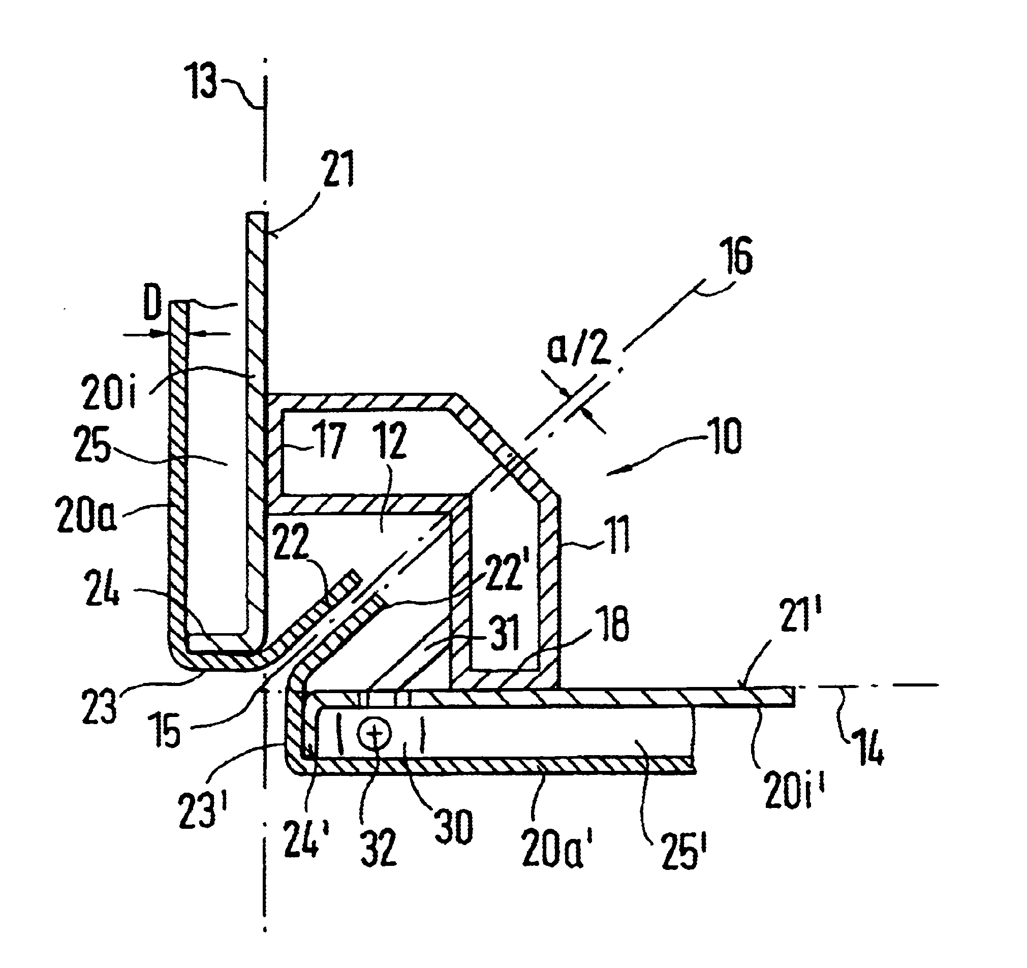
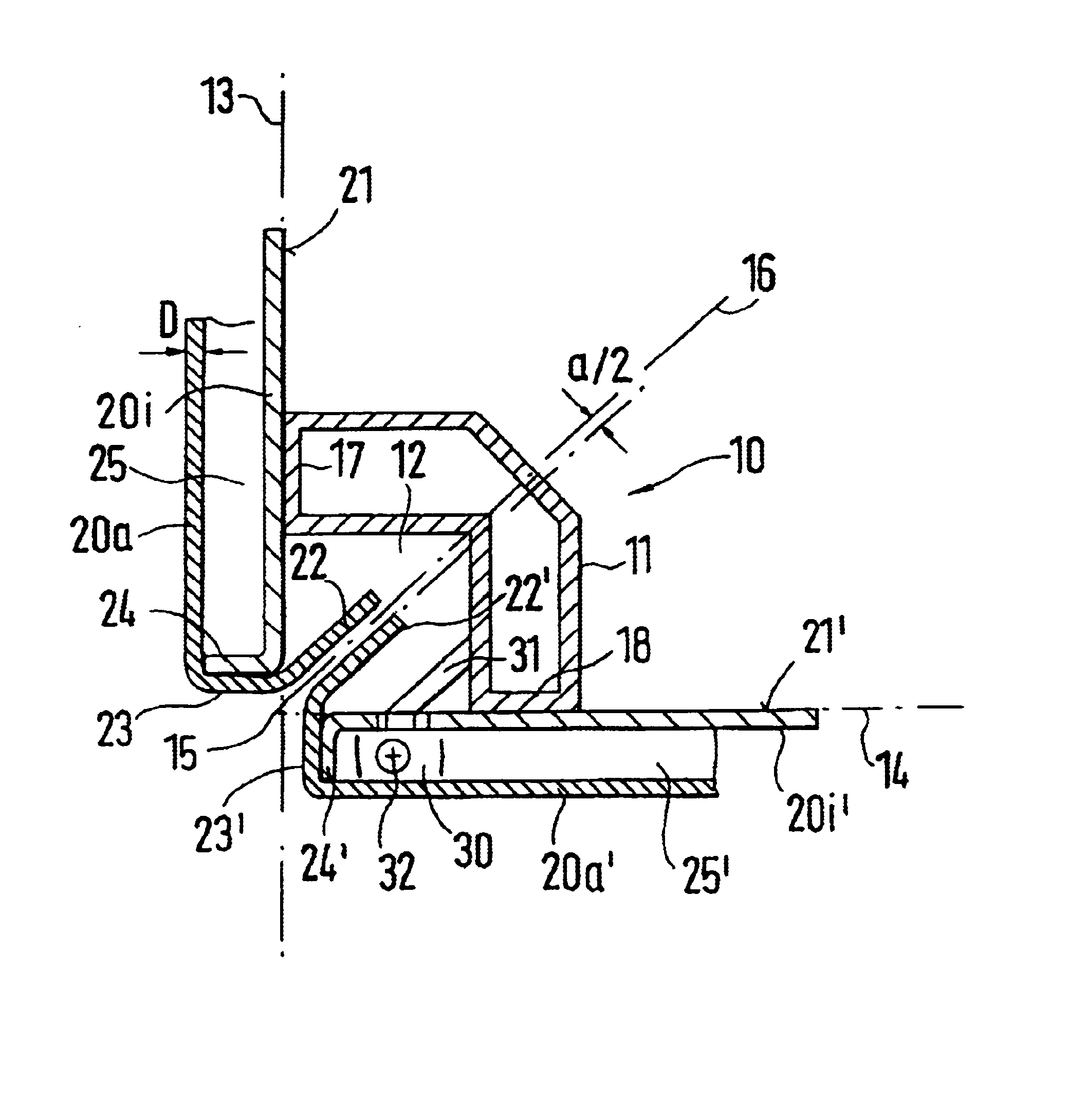
A horizontal cross-section taken through the outer edge corner 15 with the hinging side of the cabinet door according to the drawing shows, with the dot-dash line 13 and 14, the outer planes of the framework 10, which intersect at the outer edger corner 15. The outer planes 13 and 14 are defined by the outer sides of the abutment profile sides 17 and 18. The covering member with the interior wall 20i and the exterior wall 20a is mounted on the abutment profile side 17. The vertical side of the exterior wall 20a shown is double angled, as shown by the transition portion 23 and the angled end portion 22. The angled portion 22 surrounds the vertical end of the interior wall 20i, which is angled outwardly, as shown by edge 24. The edge 24 abuts the inside of the transition portion 23 and is connected thereto, for example, is welded. In the embodiment shown, the transition portion 23 is at a right angle to the exterior wall 20a and the angled end portion 22 is at an angle of 135.degree. ...


PUM


Abstract

A switchgear cabinet including rectangular frameworks of frame members, wherein, in the region of the outer corner edges, free spaces are formed for the accommodation of angled edges of the double-wall covering members, which are juxtaposed each other. At least one covering member is configured as a cabinet door, which has hinges on the framework, which is pivotally mounted with hinges and which is closable and openable by closure members on the framework. If the covering members and the cabinet doors have an interior wall and an exterior wall, the formed cavity extending at least partially over the free space of the associated vertical frame member, in the case of the cabinet doors, in the region of the covered free space, the cavity receives hinged members on the one vertical side and closure members on the opposite side. Counter-hinged members and counter-closure members are mounted on the framework, the coupling points of the hinged members and counter-hinged members being inside or outside the cavity of the cabinet door and the engagement points of the closure members and counter-closure members being in the cavity of the cabinet door, and thus precisely in the region of the hinging side and closure side of the cabinet door, safety against vandalism is improved.

Description

1. Field of the InventionThis invention relates to a switchgear cabinet including rectangular framework including frame members, wherein, in a region of the outer corner edges, free spaces are formed for the accommodation of angled edges of double-wall covering members, which are juxtaposed each other, and at least one covering member is configured as a cabinet door which is pivotally mounted on the framework by hinges and which is closable and openable by closure members on the framework.2. Description of Related ArtSwitchgear cabinets are preferably used outside and increased attention to security against unauthorized opening of the switchgear cabinets is required. A double-wall covering makes a forcible attack on the cabinet more difficult. Security against vandalism in the region of the hinging and closure side of the cabinet door is not always sufficient, as often access to the hinge and the closure is provided.It is one object of this invention, with a switchgear cabinet of th...

Claims


Application Information

Patent Timeline
Patent Type & Authority Patents(United States)
IPC IPC(8): A47B47/00A47B47/02H05K5/02H02B1/01H02B1/00H02B1/30H02B1/38H05K5/03
CPCA47B47/02H05K5/0208H05K5/0226H02B1/014
Inventor KLASSEN, SAMUELHOLIGHAUS, HEIKO
Owner RITTAL RCS COMM SYST
Why Eureka
Try Eureka