
Refuse receptacle having a charging hopper and moving floor and method therefor

a technology of receptacle and hopper, which is applied in the field of receptacle, can solve the problems of general complexity, high cost and difficulty in maintenance, and debris has a tendency to become stuck in the arms and cylinders of the control member

Inactive Publication Date: 2004-08-17
THOBE MICHAEL
View PDF7 Cites 27 Cited by
  • Summary
  • Abstract
  • Description
  • Claims
  • Application Information

AI Technical Summary

Benefits of technology

"The present invention is an improved refuse receptacle that overcomes the problems of prior art devices. The invention has a charging hopper with a curved guide surface and a control member that can be moved within the hopper to compact the material. The invention also has a control member that can be used in a multiple compartment receptacle and is easy to unload the material. The invention provides an improved solution for handling domestic refuse."

Problems solved by technology

Devices of this type suffer from the disadvantage that they are generally complicated and, as a result, expensive and difficult to maintain.
However, debris has a tendency to become stuck in the arms and cylinders of the control member.
Furthermore, the control member is only designed to work in a single compartment refuse receptacle.

Method used


Image

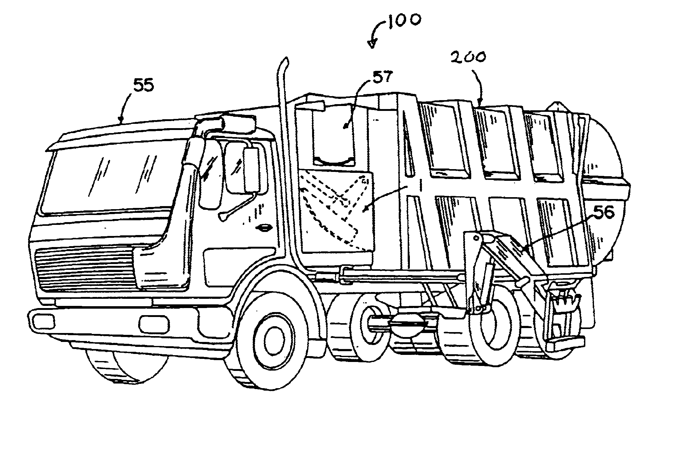
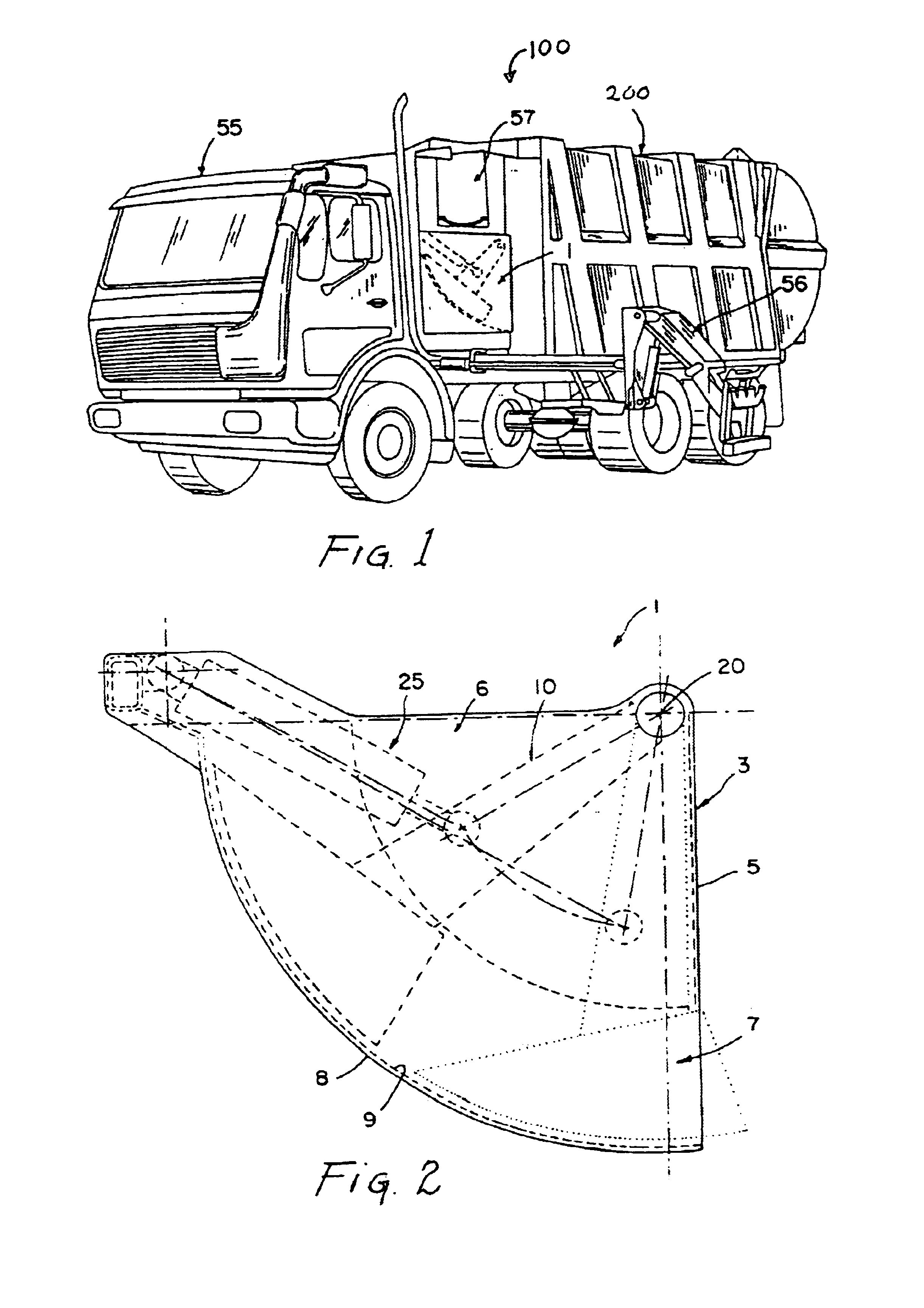
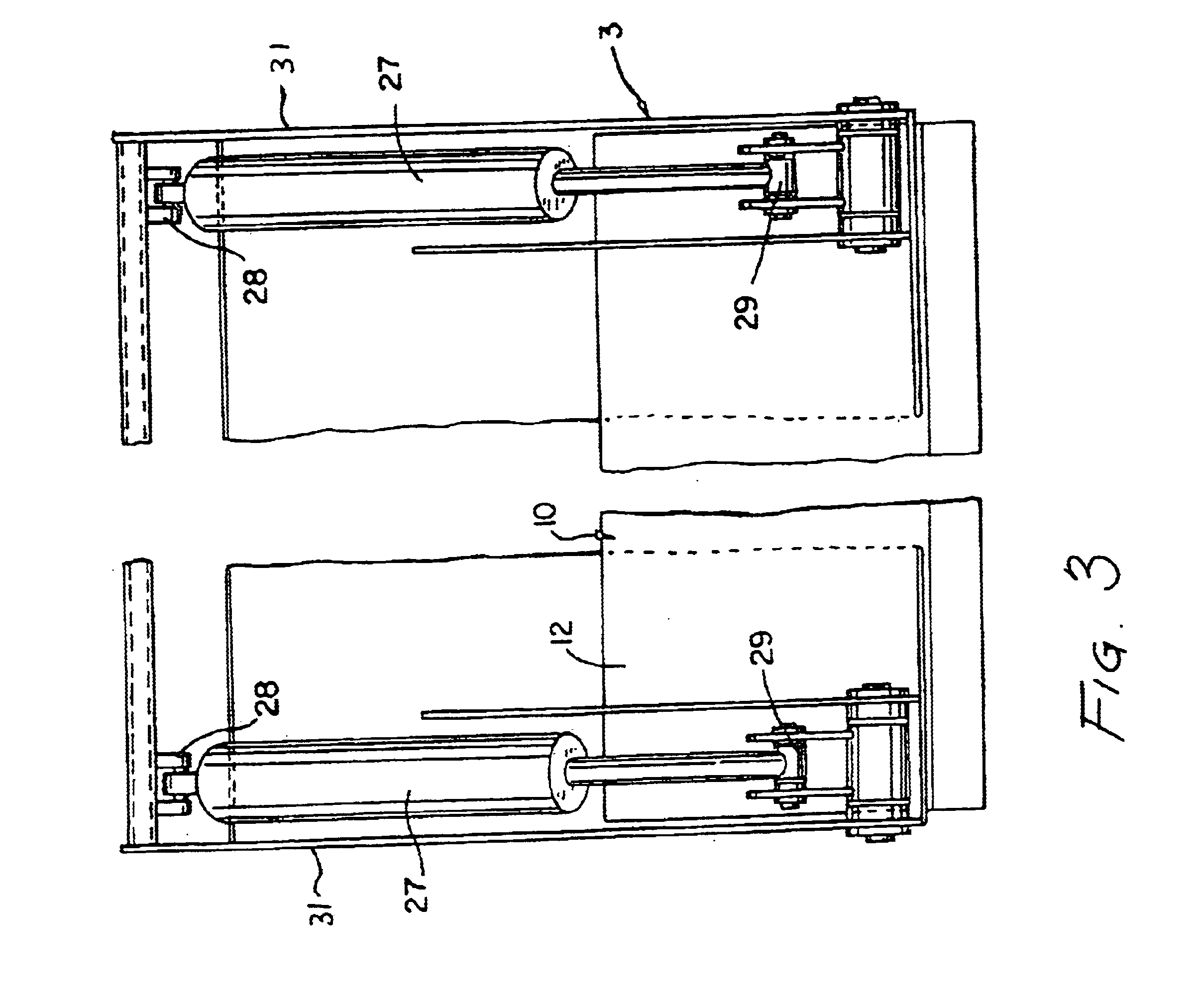
  • Refuse receptacle having a charging hopper and moving floor and method therefor
  • Refuse receptacle having a charging hopper and moving floor and method therefor
  • Refuse receptacle having a charging hopper and moving floor and method therefor

Examples


Embodiment Construction

In accordance with one embodiment of the present invention, a refuse handling apparatus having a collection receptacle is disclosed. The collection receptacle on the refuse handling apparatus has a charging hopper having a first opening for loading material into the charging hopper, a second opening through which material can be discharged from the charging hopper, the second opening being disposed below the first opening when the apparatus is in use. The charging hopper has a curved guide surface therein which extends between the first and second openings so as to form a slide for directing material towards the second opening. A control member is provided and has a work head which is mounted for movement within the charging hopper about a pivot axis which extends generally horizontally when the apparatus is in use. The control member is pivotally movable about the pivot axis between a first position in which the work head is spaced from and disposed above the second opening, and a ...


PUM


Abstract

A material handling apparatus comprising a charging hopper having an upper first opening through which material can be loaded into the charging hopper and a lower second opening through which material can be discharged from the charging hopper. The apparatus includes a control member having a work head having one or more sections which is mounted for movement within the charging hopper about a pivot axis which extends generally laterally with respect to the normal upright operative position of the apparatus. The control member is pivotally movable about the pivot axis between a first position in which the work head is spaced from and disposed above the second opening, and a second position in which the work head is adjacent or within the second opening. The control member has a plurality of arms for pivotally mounting control member. A pivot bar is coupled to the mounting arms for maintaining stability between the mounting arms and to ensure proper movement of the control member.

Description

1. Field of the InventionThis invention relates generally to a refuse receptacle and, more specifically, to a refuse receptacle having an improved charging hopper for compacting the refuse and a walking floor to remove the refused from the receptacle.2. Description of the Prior ArtRefuse receptacles have been in use for a long time. One type of refuse handling apparatus includes a loading mechanism which feeds refuse to a holding receptacle whenever the refuse is compressed or compacted by a ram or press which forms part of the loading mechanism. Such apparatus is usually mounted on a truck or like vehicle and can be used in the collection of domestic refuse. Examples of such devices are described in U.S. Pat. Nos. 3,874,529, 3,881,613, 4,050,594, 4,298,306, 4,637,306 and 4,786,228. Devices of this type suffer from the disadvantage that they are generally complicated and, as a result, expensive and difficult to maintain.U.S. Patent 5,324,161 discloses a refuse receptacle charging ho...

Claims


Application Information

Patent Timeline
Patent Type & Authority Patents(United States)
IPC IPC(8): B30B9/00B30B9/30
CPCB30B9/3082B65F3/208B65F3/24
Inventor THOBE, MICHAELTHOBE, HELMUT OTTO BRUNO
Owner THOBE MICHAEL
Learn More