
Railway vehicle and device for accessing said vehicle

a technology for railways and vehicles, applied in railway stations, transportation and packaging, roads, etc., can solve the problems of lowering and tilting of vehicles, presenting passengers with reduced mobility, and unable to allow persons with reduced mobility to gain access to vehicles from all railway platforms, so as to reduce distance

Inactive Publication Date: 2011-03-22
ALSTOM TRANSPORT TECH SAS
View PDF39 Cites 10 Cited by
  • Summary
  • Abstract
  • Description
  • Claims
  • Application Information

AI Technical Summary

Benefits of technology

The solution allows individuals with reduced mobility to access the vehicle independently and safely without steps, reducing the risk of falls and ensuring the vehicle can accommodate varying platform heights and shapes, facilitating easy movement with ramps less than 8% gradient.

Problems solved by technology

Such a vehicle has the disadvantage of presenting a risk to passengers when a step is created between the movable plate and the floor of the adjacent passenger areas.
In addition, owing to those steps, persons with reduced mobility who access the movable plate, from a railway platform, when it is in the access position do not have access to the rest of the vehicle; such persons must wait until the movable plate of the access platform is repositioned in the same plane as the floor of the passenger zones in order to gain access to the rest of the vehicle.
In addition, the vehicle of the prior art, in which the plate is movable vertically, has the disadvantage that it does not allow persons with reduced mobility to gain access to the vehicle from all railway platforms without assistance.
In addition, wear of the wheels and compression of the vehicle suspension causes lowering and tilting of the vehicle.
A vehicle of the prior art has the disadvantage that it does not always allow persons with reduced mobility to gain access to the vehicle from a railway platform without assistance because the space that is left between the movable plate and the railway platform can be important.

Method used


Image

  • Railway vehicle and device for accessing said vehicle
  • Railway vehicle and device for accessing said vehicle
  • Railway vehicle and device for accessing said vehicle

Examples


Embodiment Construction

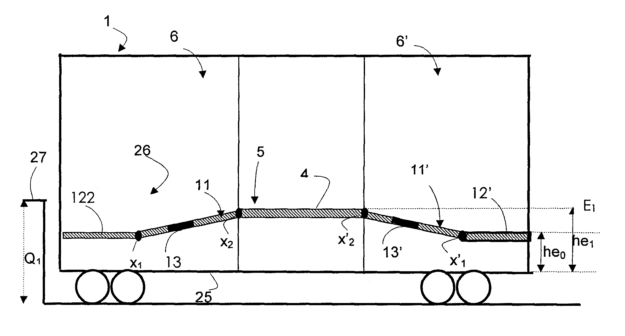
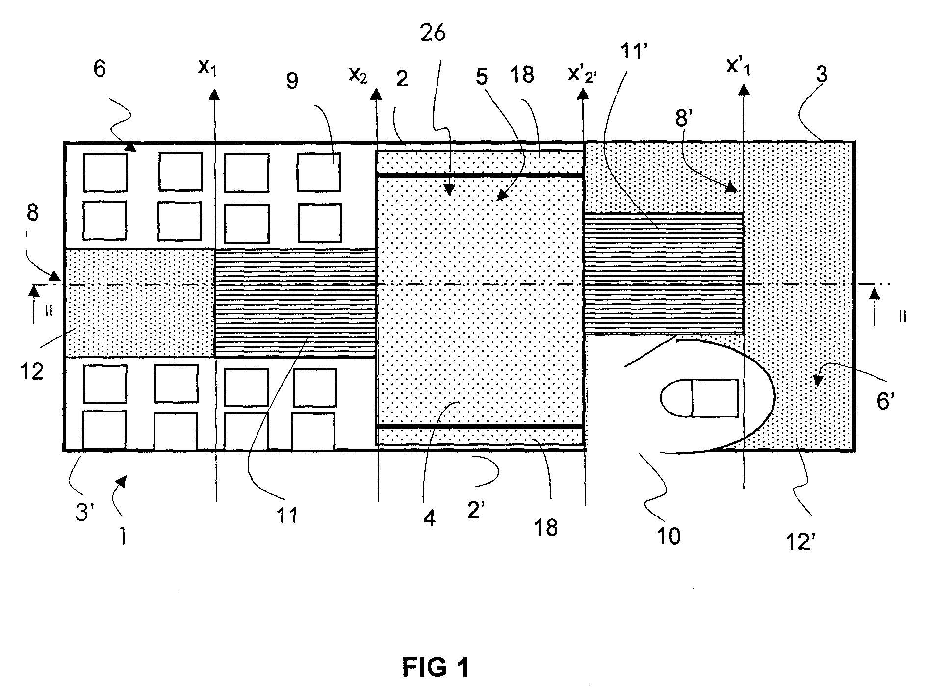
[0038]As is shown in FIG. 1, a railway vehicle 1 comprises two doors 2 and 2′ which are opposite one another and are provided in the two lateral walls 3 and 3′ of the vehicle.

[0039]The vehicle comprises an access device 26 comprising an access platform 4 which extends transversely between the two lateral walls 3 and 3′ and longitudinally over the entire width of the access doors 2 and 2′.

[0040]In another embodiment, only one lateral face 3 comprises an access door 2, behind which the platform 4 extends.

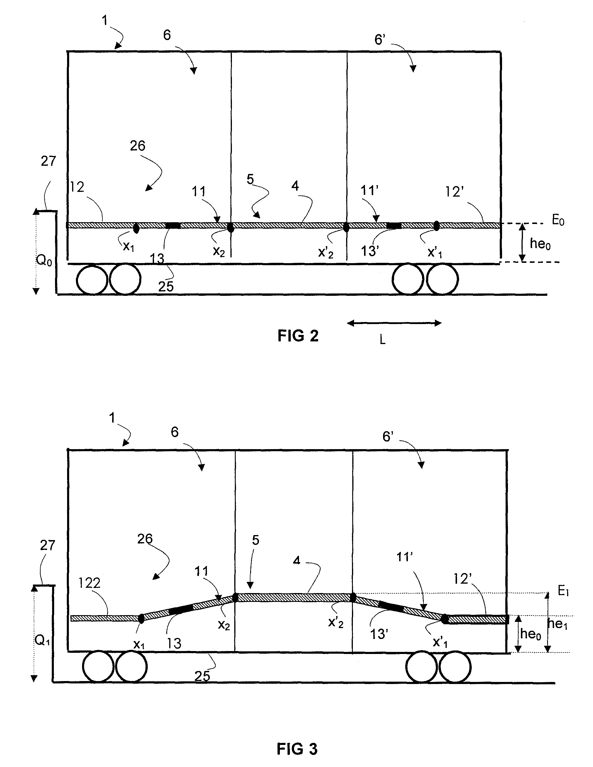
[0041]The platform 4 comprises a vertically movable plate 5. “Vertically movable” is understood as meaning that the plate is capable of moving in a direction perpendicular to the plane formed by the chassis 25 of the vehicle.

[0042]In the embodiment shown in FIG. 1, the plate 5 extends over the entire length of the access platform 4. The movable plate 5 extends transversely between two adjusting means 18 and 18′. The adjusting means 18 and 18′ extend between the movable plate 5 and an ...


PUM


Abstract

A railway vehicle including an access platform which extends between two lateral faces, at least one of the faces having a lateral access door. The access platform is adjacent a passenger area and includes a plate which is movable vertically so as to allow passengers with reduced mobility to access / leave the access platform from / to a railway platform of a given height when the movable plate is placed in a given embarkation / disembarkation position. Also included is a moving floor allowing persons with reduced mobility to move between said passenger area and said movable plate whatever the embarkation / disembarkation position thereof. The moving floor is located and always remains in an interior of the vehicle along with the passenger area and the movable plate between which the moving floor is located.

Description

BACKGROUND OF THE INVENTION[0001]The invention relates to a railway vehicle comprising an access platform which extends transversely between two lateral faces, said access platform being adjacent to at least one passenger zone. The access platform comprises a plate which is movable vertically so as to allow persons with reduced mobility to gain access to the vehicle from railway platforms of different heights.[0002]Such a vehicle is described in patent application DE19914965. The above-mentioned patent application describes a vehicle comprising a movable plate which has a position in which the movable plate and the floor of the passenger zones are coplanar. The movable plate is displaced vertically in order to allow persons with reduced mobility to gain access to the vehicle from a railway platform the height of which is different from the height of the floor of the passenger zones.[0003]When the movable plate is displaced vertically, a step is created, in the vehicle, between the m...

Claims


Application Information

Patent Timeline
Patent Type & Authority Patents(United States)
IPC IPC(8): B61D17/00
CPCA61G3/066B61D13/00B61D17/10B61D23/00B61D23/02
Inventor PUJOL, CLAUDE
Owner ALSTOM TRANSPORT TECH SAS
Learn More