System and method for I-Q mismatch compensation in a low IF or zero IF receiver

a receiver and iq mismatch technology, applied in the field of wireless communication, can solve the problems of not allowing conventional filtering, requiring additional circuitry, power consumption and additional expense to build the device, and output signals i(t) and q(t) that are not allowed

Inactive Publication Date: 2004-08-31
QUALCOMM INC
View PDF7 Cites 98 Cited by
  • Summary
  • Abstract
  • Description
  • Claims
  • Application Information

AI Technical Summary

Problems solved by technology

However, this architecture requires additional circuitry, power consumption and additional expense to build the device.
However, the IF is a very low frequency and thus does not permit the conventional filtering to remove the undesirable image band interference as is common in heterodyne architectures, as described above.
Unfortunately, such ideal circuits do not exist.
This undesirable circuit mismatch in the I and Q circuits results in output signals I(t) and Q(t) that are not truly orthogonal.
Those portions of the spectrum are undesirable and are readily removed using conventional techniques.
In addition, portion 36i, representing the J_60 image spectra, is centered at 45 kHz and may also cause significant interference with the desired signal.
However, circuit matching cannot completely eliminate the mismatch local oscillator signal.
Circuit differences in the first and second mixers and / or first and second filters result in gain and / or phase errors that result in mismatch in the I and Q output signals.

Method used


Image

  • System and method for I-Q mismatch compensation in a low IF or zero IF receiver
  • System and method for I-Q mismatch compensation in a low IF or zero IF receiver
  • System and method for I-Q mismatch compensation in a low IF or zero IF receiver

Examples


Embodiment Construction

The present invention provides active correction of the I(t) and Q(t) signals to overcome the inherent mismatch and the resultant detrimental effects. As will be described in greater detail below, each communication device is unique and, in an exemplary embodiment, undergoes calibration at the factory. The calibration factors are stored in the device and used to automatically generate the compensated signals.

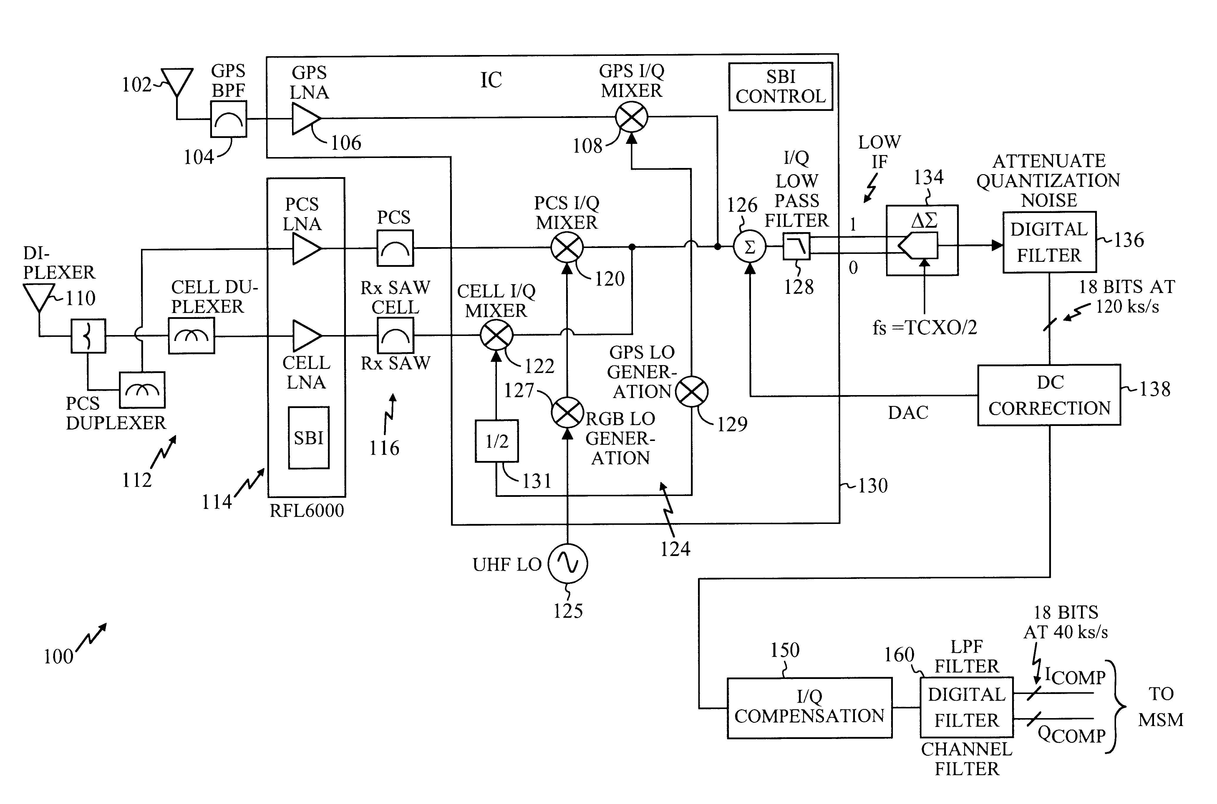
In an exemplary embodiment, the present invention is embodied in a system 100 illustrated in the functional block diagram of FIG. 3. As can be seen by the block diagram of FIG. 3, the present invention is applicable to any quadrature receiver, such as an advanced mobile phone system (AMPS), a global positioning system (GPS) receiver, a conventional cell phone system, or a PCS system. The GPS embodiment may include a GPS antenna 102, a filter 104, an amplifier 106, and an I-Q mixer circuit 108. Those skilled in the art will recognize that the I-Q mixer circuit 108 illustrates a s...


PUM


Abstract

A compensation circuit to correct for mismatch in a quadrature receiver comprises first and second mixers to receive a radio frequency (RF) modulated signal. One mixer receives an I local oscillator signal while the second mixer receives a Q local oscillator signal wherein the I and Q local oscillators have frequencies that are substantially identical. The output of the first and second mixers are coupled to first and second filters, respectively, which generate the I and Q output signals, respectively. Inherent circuit mismatch generate gain and / or phase errors that result in mismatch in the I and Q output signals. A correction circuit automatically applies a correction factor to at least one of the I and Q output signals to correct the gain and / or phase error by applying a multiplication factor to at least one of the I and Q output signals to thereby generate a corrected signal. The correction factors must be determined on a unit by unit basis. Testing in the final stages of factory assembly may be used to determine the value of the correction factor. The correction factor may be stored in a memory of the wireless communication device and used thereafter.

Description

1. Technical FieldThe disclosed system and method generally relates to the field of wireless communications. More particularly, the disclosed system and method relates to a system and method for compensating for I-Q mismatch in a low intermediate frequency (IF) or zero IF receiver.2. Description of Related ArtRadio receivers, such as a heterodyne receiver, have long been used for radio communication. With a heterodyne architecture, a radio frequency signal is detected by a tuner, or other radio frequency device coupled to an antenna. An internal oscillator, called a local oscillator, is supplied to a mixer along with the radio frequency signal. The mixer produces output signals at both the sum and difference between the radio frequency and the local oscillator. The output of this stage is usually designated as an intermediate frequency (IF). Because the IF is still relatively high frequency, conventional filtering techniques may be used to eliminate one set of output signals from th...

Claims


Application Information

Patent Timeline
Patent Type & Authority Patents(United States)
IPC IPC(8): H03D3/00H04B1/30H04L27/00
CPCH03D3/009H04B1/30H04L2027/0016H04L2027/0024
Inventor CICCARELLI, STEVEN C.RAGHUPATHY, ARUNREEVES, ROBERT
Owner QUALCOMM INC
Why Eureka
Try Eureka