Low noise image reject mixer and method therefor

Active Publication Date: 2006-03-16
XENOGENIC DEV LLC
View PDF29 Cites 53 Cited by
  • Summary
  • Abstract
  • Description
  • Claims
  • Application Information

AI Technical Summary

Problems solved by technology

One well-known problem with the mixing process is that it creates image signals.
However for other systems the attenuation of the RF bandpass filter is not sufficient.
However known mixer archit

Method used


Image

  • Low noise image reject mixer and method therefor
  • Low noise image reject mixer and method therefor
  • Low noise image reject mixer and method therefor

Examples


Embodiment Construction

[0020] The following detailed description is merely exemplary in nature and is not intended to limit the invention or the application and uses of the invention. Furthermore, there is no intention to be bound by any expressed or implied theory presented in the preceding technical field, background, brief summary or the following detailed description.

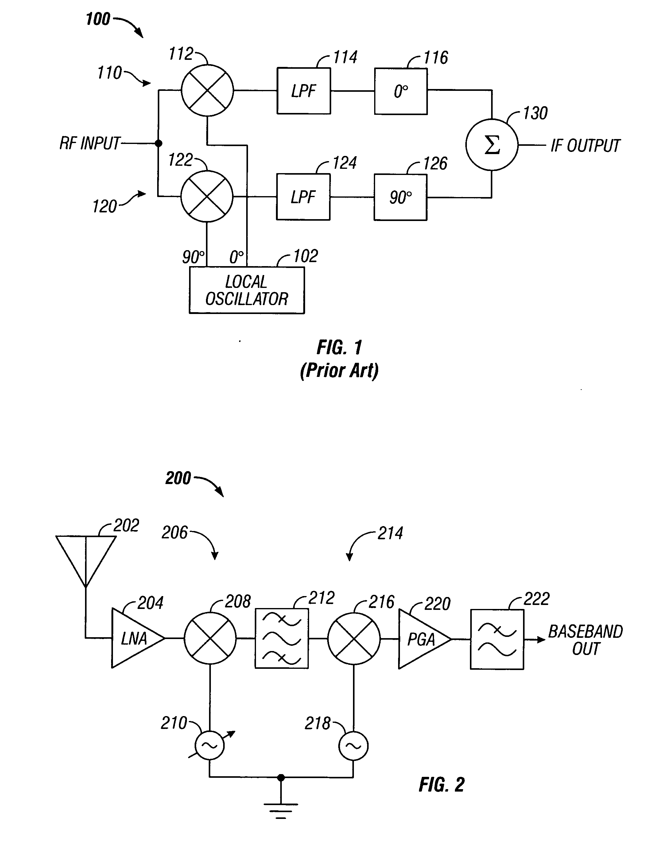
[0021]FIG. 1 illustrates in partial block diagram and partial schematic form an image reject mixer 100 known in the prior art. Image reject mixer 100 includes a local oscillator 102 that generates an in-phase local oscillator signal labeled “0°” and a quadrature local oscillator signal labeled “90°”. Alternatively the phase shifts could be +45° and −45° respectively. These signals are utilized in an in-phase path 110 and a quadrature path 120. In-phase path 110 includes a multiplier 112, a lowpass filter 114, and a phase shifter 116. Multiplier 112 that has a first input terminal for receiving a radio frequency (RF) input signal labeled ...


PUM


Abstract

A receiver (200) includes a transconductance mixer (310), a polyphase filter (320), and a transimpedance amplifier (330). The transconductance mixer (310) mixes a radio frequency (RF) voltage signal into a current signal having a plurality of phases using a local oscillator signal. The polyphase filter (320) filters the current signal to provide a filtered current signal. The transimpedance amplifier (330) converts the filtered current signal into an output voltage signal.

Description

CROSS REFERENCE TO RELATED APPLICATIONS [0001] Related subject matter is contained in copending patent Application No. 10 / 779,100, filed on Feb. 11, 2004, entitled “Radio Frequency Low Noise Amplifier with Automatic Gain Control” invented by Andrew W. Krone and assigned to the assignee hereof.TECHNICAL FIELD [0002] The present invention generally relates to frequency conversion circuits, and more particularly to mixers. BACKGROUND [0003] Radio frequency (RF) receivers are used in a wide variety of applications such as television, cellular telephones, pagers, global positioning system (GPS) receivers, cable modems, cordless phones, satellite radio receivers, and the like. As used herein, a “radio frequency” signal means an electrical signal conveying useful information and having a frequency from about 3 kilohertz (kHz) to thousands of gigahertz (GHz), regardless of the medium through which such signal is conveyed. Thus an RF signal may be transmitted through air, free space, coaxial...

Claims


Application Information

Patent Timeline
IPC IPC(8): H04Q7/20
CPCH03D7/1441H03D7/165H03D7/1483H03D7/1458
Inventor THOMPSON, CHARLES D.LEE, EDWARD KIM FUNG
Owner XENOGENIC DEV LLC
Why Eureka
Try Eureka