Hearing aid with large diaphragm microphone element including a printed circuit board

Inactive Publication Date: 2006-02-21
HIMPP
View PDF16 Cites 138 Cited by
  • Summary
  • Abstract
  • Description
  • Claims
  • Application Information

AI Technical Summary

Benefits of technology

[0006]This invention is directed in particular, to disposable hearing aids, i.e., inexpensive hearing aids capable of lasting at least a limited period of time. Traditional hearing aids use microphones having relatively small size diaphragms, generally of the capacitive or electret type. Microphones for the hearing aid industry have continually become smaller in design, allowing hearing aids to also become smaller. However, as these micropho

Problems solved by technology

However, as these microphones become smaller, they tend to become more expensive.
However, a single large diaphragm has the problem of instabili

Method used


Image

  • Hearing aid with large diaphragm microphone element including a printed circuit board
  • Hearing aid with large diaphragm microphone element including a printed circuit board
  • Hearing aid with large diaphragm microphone element including a printed circuit board

Examples


Embodiment Construction

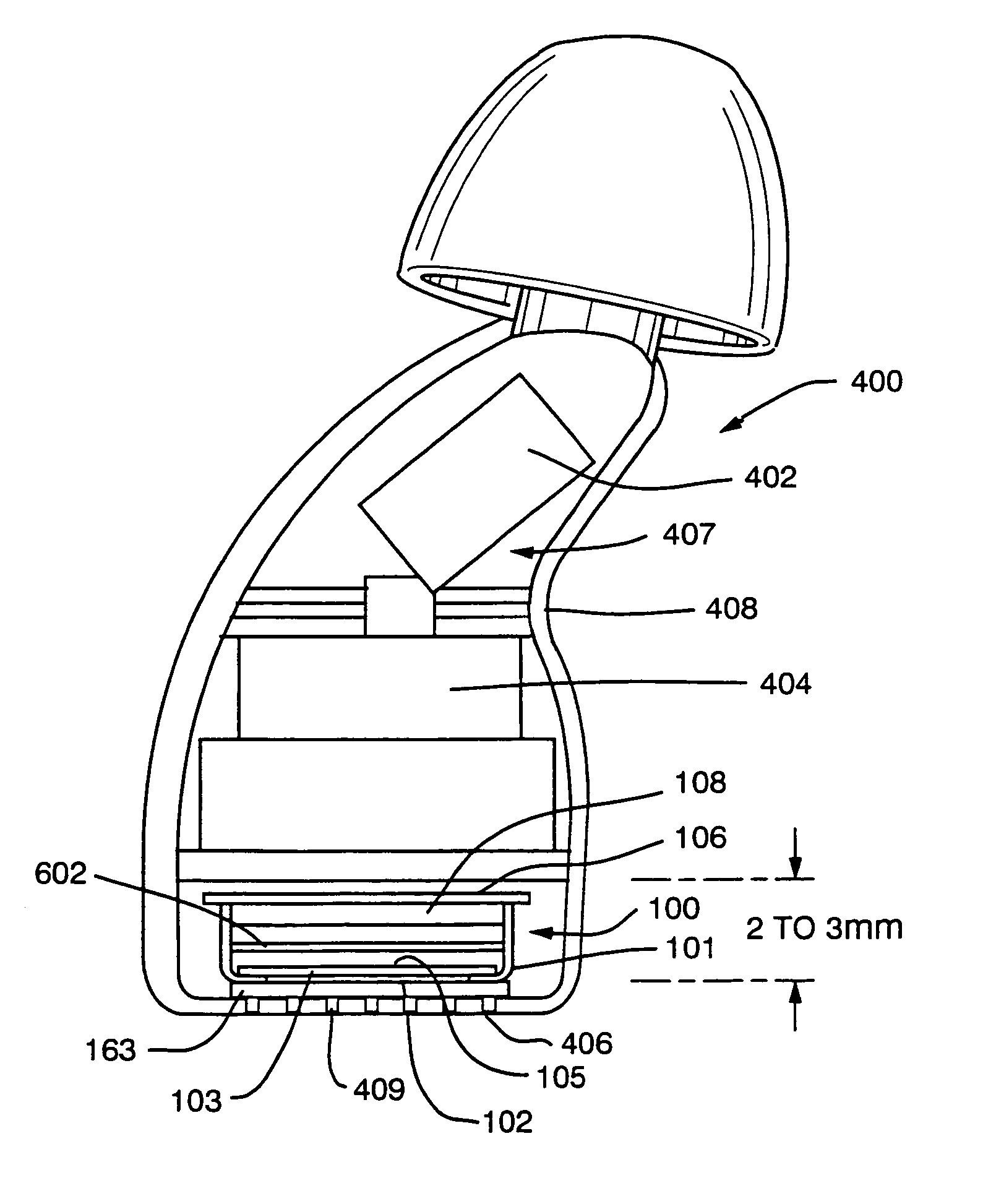
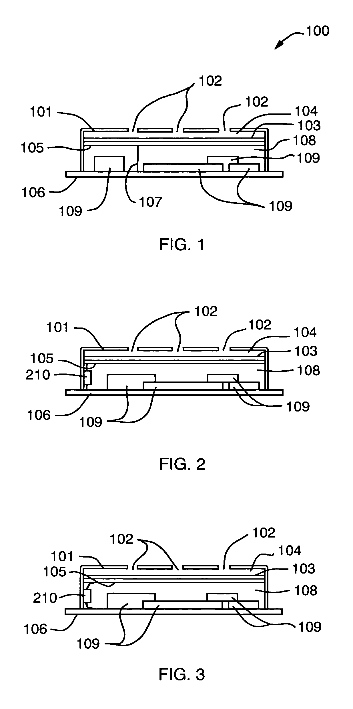
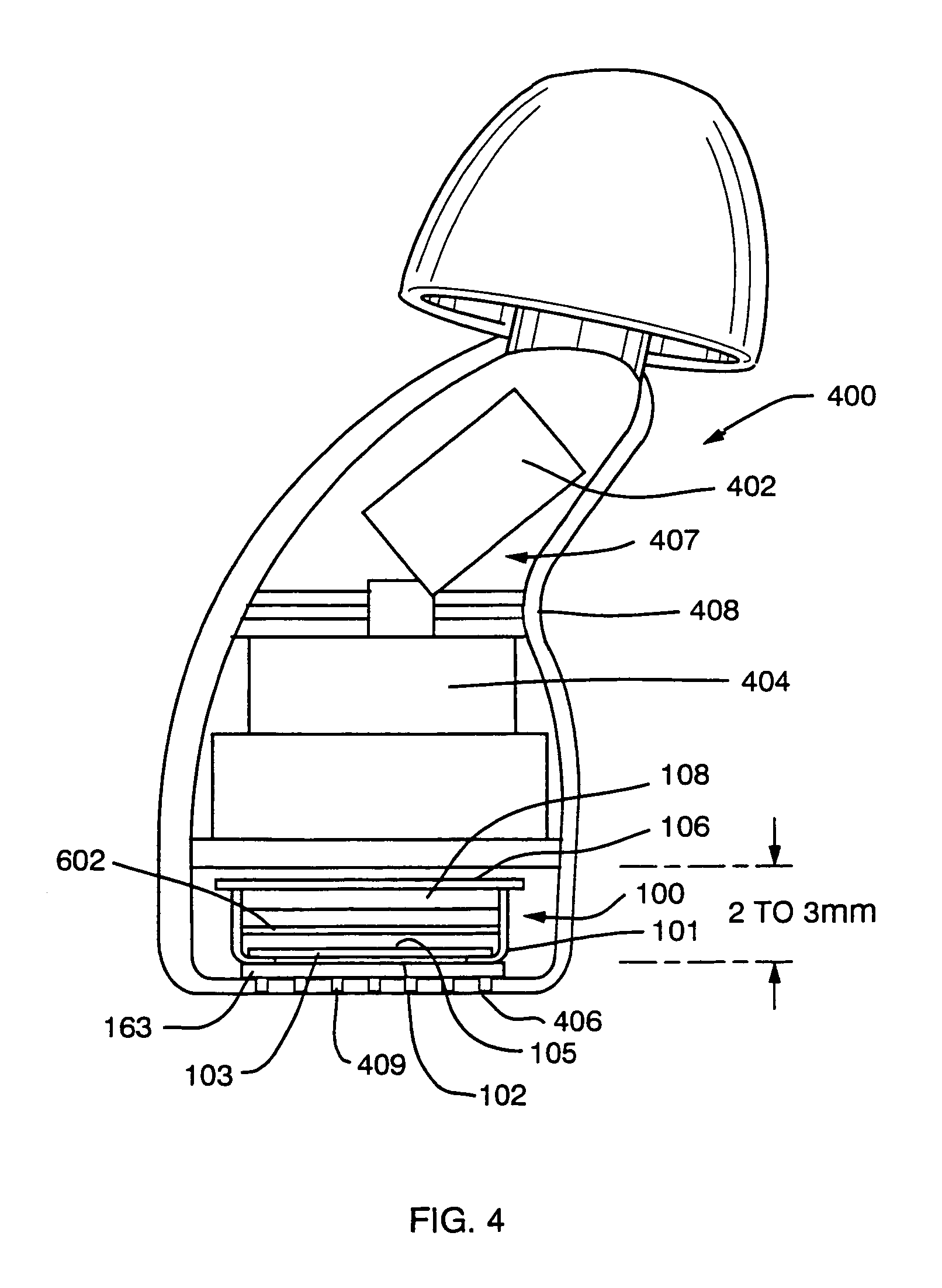
[0055]FIG. 1 shows a first embodiment of the invention illustrated pictorially in a cross sectional view of a hearing aid microphone assembly 100. A metal housing 101 adapted to be disposed inside an enclosure such as the enclosure 408 shown in FIG. 4; with sound inlets 102 contains, inter alia, front chamber 104, a diaphragm 103, a backplate 105, a back chamber 108, and electrical components 109. In addition, a printed circuit board 106 on which the components are mounted, and an electrical connection 107 is included in the housing 101, thereby providing all the electrical components (except the battery and a receiver) required for a hearing aid. The diaphragm 103 consists of a sheet of a thin flexible material (e.g., metallized mylar) that is stretched tight and glued to a support element 501. As shown in FIGS. 5 and 6, the support element 501 may take many shapes. In the FIGS. 5 and 6 embodiments, a separate spacer is inserted between the diaphragm (with its support element) and ...


PUM


Abstract

A disposable-type hearing aid uses a relatively large single diaphragm or a large single diaphragm subdivided into a plurality of smaller active diaphragm areas obtained using a grate-like back support plate with ridges which contact and divide the diaphragm into the several smaller active diaphragm areas. The diaphragm and a backplate are enclosed in a metal housing and are disposed proximal and parallel to a shell-like hearing aid enclosure having sound inlets. The metal housing is closed at an end opposite the sound inlets by a printed circuit board (PCB) forming an acoustical seal for a back volume of the microphone. The PCB also carries substantially all the electronic components for the hearing aid thereon. The PCB has a ground plane in contact with the housing whereby the PCB also acts as an EMI shield. An electrical connection is formed in various ways between the back support plate and the PCB during assembly of the metal housing and components with the PCB. Mass production of disposable hearing aids with large diaphragms and relatively low noise levels is thus possible using this invention.

Description

RELATED APPLICATIONS[0001]This application claims the benefit of U.S. Provisional Application Ser. No. 60 / 115,011, filed on Jan. 7, 1999, U.S. Provisional Application Ser. No. 60 / 134,896, filed May 19, 1999 and U.S. Provisional Application Ser. No. 60 / 157,872, filed Oct. 6, 1999, and U.S. patent application entitled “Microphone Assembly for Hearing Aid With JFET Flip-Chip Buffer”, filed date on Jan. 6, 2000, now U.S. Pat. No. 6,366,678, the contents of each of which is incorporated herein by reference.BACKGROUND OF THE INVENTION[0002]The performance of a hearing aid depends, among other things, upon the design of the microphone pickup. The microphone is a substantial part of the hearing aid. Further, where a hearing aid uses a circuit board which requires electrical connections to be completed during the hearing aid assembly, the ease and simplicity with which the electrical connections can be made impacts the cost of manufacture. Hearing aids which can be manufactured at relatively...

Claims


Application Information

Patent Timeline
IPC IPC(8): H04R25/00
CPCH04R19/016H04R25/604H04R25/65H04R25/60H04R25/00H04R25/609
Inventor SJURSEN, WALTER P.MAHONEY, DEREK D.MARGICIN, JOHN M.FRITZ, FREDERICK J.ACETI, JOHN G.PREVES, DAVID A.PALANISAMY, PONNUSAMY
Owner HIMPP
Why Eureka
Try Eureka