Radio frequency filter using intermediate frequency impedance translation

a technology of impedance translation and radio frequency, applied in the field of radio frequency filter, can solve the problems of difficult to produce an rf bandpass filter with a high enough q to adequately filter out all unwanted signals and noise, and the roll-off characteristics of rf bandpass filters are typically limited, so as to improve intermodulation performance, translate the impedance, and effectively translate and preserve the if impedance characteristics

Active Publication Date: 2010-10-05
HUAWEI TECH CO LTD
View PDF10 Cites 53 Cited by
  • Summary
  • Abstract
  • Description
  • Claims
  • Application Information

AI Technical Summary

Benefits of technology

[0005]The present invention is an RF filter that translates impedances of an IF circuit to create a filter with an RF center frequency having the high Q roll-off characteristics of an IF filter. The RF filter is self-aligned with the frequency of an RF local oscillator. The RF filter has an impedance divider, which is formed by coupling an RF impedance circuit to a translated IF impedance circuit. The translated IF impedance circuit includes an RF passive mixer and an IF impedance circuit. The mixer translates the impedance of the IF impedance circuit by mixing an RF input signal with an RF local oscillator signal, which determines the RF center frequency. Filtered RF signals may be provided by the impedance divider. In addition, filtered IF signals may be provided by the IF impedance circuit. To effectively translate and preserve the IF impedance characteristics, the IF impedance circuit presents a high impedance at harmonics of the RF local oscillator signal. Several different types of RF filters can be created using this technique, including but not limited to RF bandpass filters, RF notch filters, and RF double notch filters. Such filters could be used in RF transmitters, RF receivers, or both. By removing interfering signals in the RF section of an RF receiver instead of the IF section, the RF mixer is spared large amplitudes of interfering signals, which can significantly improve intermodulation performance, relax compression point requirements in the IF section, or both.
[0006]In certain embodiments of the present invention, the RF impedance circuit may be series coupled in an RF signal path, and the translated IF impedance circuit may be coupled to ground. The RF passive mixer and the IF impedance circuit may be quadrature to eliminate image load impedances creating image responses as a result of mixing. RF signals, IF signals, or both may include differential signals. The RF passive mixer may be a switching RF passive mixer, which uses the RF local oscillator signal to enable and disable switching elements between an RF input and an IF output. The RF impedance circuit may be provided by an output impedance of an RF amplifier that feeds the translated IF impedance circuit. An RF receiver may use the present invention to remove unwanted signals that have been received through an antenna, or signals from other circuitry, such as an RF transmitter. An RF receiver may use filtered IF signals from the IF impedance circuit. The filtered IF signals may be at any IF frequency, including but not limited to very low IF (VLIF) and direct current (DC) resulting from direct conversion. An RF transmitter may use the present invention to remove noise from a transmitted signal.

Problems solved by technology

RF bandpass filters are typically limited in their roll-off characteristics.
It is difficult to produce an RF bandpass filter with a high enough Q to adequately filter out all of the unwanted signals and noise.

Method used


Image

  • Radio frequency filter using intermediate frequency impedance translation
  • Radio frequency filter using intermediate frequency impedance translation
  • Radio frequency filter using intermediate frequency impedance translation

Examples


Embodiment Construction

[0031]The embodiments set forth below represent the necessary information to enable those skilled in the art to practice the invention and illustrate the best mode of practicing the invention. Upon reading the following description in light of the accompanying drawing figures, those skilled in the art will understand the concepts of the invention and will recognize applications of these concepts not particularly addressed herein. It should be understood that these concepts and applications fall within the scope of the disclosure and the accompanying claims.

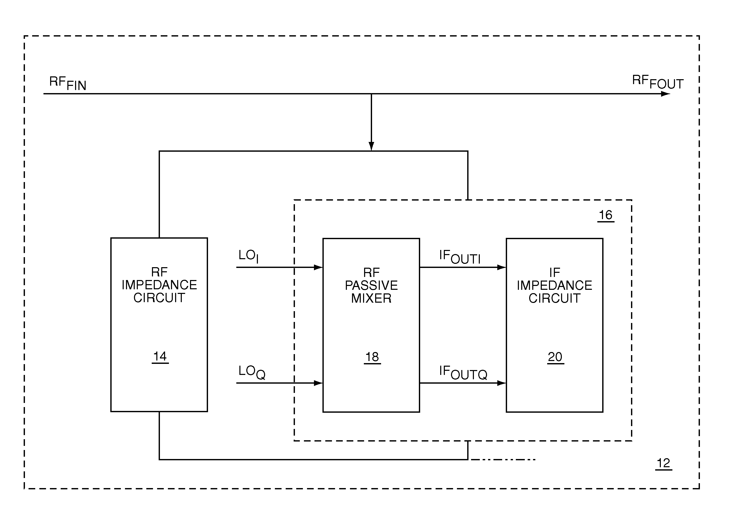
[0032]The present invention is an RF filter that translates impedances of an IF circuit to create a filter with an RF center frequency having the high Q roll-off characteristics of an IF filter. The RF filter is self-aligned with the frequency of an RF local oscillator. The RF filter has an impedance divider, which is formed by coupling an RF impedance circuit to a translated IF impedance circuit. The translated IF impedance circu...


PUM


Abstract

The present invention is an RF filter that translates impedances of an IF circuit to create a filter with an RF center frequency having the high Q roll-off characteristics of an IF filter. The RF filter is self-aligned with the frequency of an RF local oscillator. The RF filter has an impedance divider, which is formed by coupling an RF impedance circuit to a translated IF impedance circuit. The translated IF impedance circuit includes an RF passive mixer and an IF impedance circuit. The mixer translates the impedance of the IF impedance circuit by mixing an RF input signal with an RF local oscillator signal, which determines the RF center frequency. Filtered RF signals may be provided by the impedance divider. Filtered IF signals may be provided by the IF impedance circuit. To effectively translate and preserve the IF impedance characteristics, the IF impedance circuit presents a high impedance at harmonics of the RF local oscillator signal.

Description

[0001]This U.S. patent application claims the benefit of provisional patent application Ser. No. 60 / 829,994, filed Oct. 18, 2006, the disclosure of which is hereby incorporated by reference in its entirety.FIELD OF THE INVENTION[0002]The present invention relates to radio frequency (RF) filters, which are used in RF communications systems.BACKGROUND OF THE INVENTION[0003]RF filters are commonly used in RF communications circuits to remove signals at unwanted RF frequencies. An RF receiver may use RF filters to remove unwanted signals that have been received through an antenna, or signals from other circuitry, such as an RF transmitter. An RF transmitter may use RF filters to remove noise from a transmitted signal. A common type of filter circuit is a surface acoustic wave (SAW) filter, which may be used as a bandpass filter. One example of a bandpass filter 10 is shown in FIG. 1. A filter input FIN feeds the bandpass filter 10, which filters out high frequency signals and low freque...

Claims


Application Information

Patent Timeline
Patent Type & Authority Patents(United States)
IPC IPC(8): H04B1/16H04B1/26
CPCH04B1/28
Inventor GRANGER-JONES, MARCUSMCKAY, THOMAS
Owner HUAWEI TECH CO LTD
Why Eureka
Try Eureka