Moving-magnet linear motor, aligner and apparatus provided therewith, and method for manufacturing devices using the same

a linear motor and magnet technology, applied in the direction of photomechanical equipment, instruments, propulsion systems, etc., can solve the problems of increasing the amount of heat produced by the linear motor, deteriorating the positioning accuracy of the linear motor, and not energized coils

Inactive Publication Date: 2004-09-14
CANON KK
View PDF13 Cites 28 Cited by
  • Summary
  • Abstract
  • Description
  • Claims
  • Application Information

AI Technical Summary

Problems solved by technology

However, these coils are not energized at the instant of switch-over.
The cogging force occurs regardless of the existence of the energizing current, and deteriorates the positioning accuracy of the linear motor.
Also, the cogging force requires additional energizing current for the linear motor to produce a necessary thrust force and thereby causes the amount of heat produced by the linear motor to increase.
However, these methods only remove specific harmonic components of the cogging force and have not managed to completely eliminate the cogging force, including the harmonic components thereof.

Method used


Image

  • Moving-magnet linear motor, aligner and apparatus provided therewith, and method for manufacturing devices using the same
  • Moving-magnet linear motor, aligner and apparatus provided therewith, and method for manufacturing devices using the same
  • Moving-magnet linear motor, aligner and apparatus provided therewith, and method for manufacturing devices using the same

Examples


first embodiment

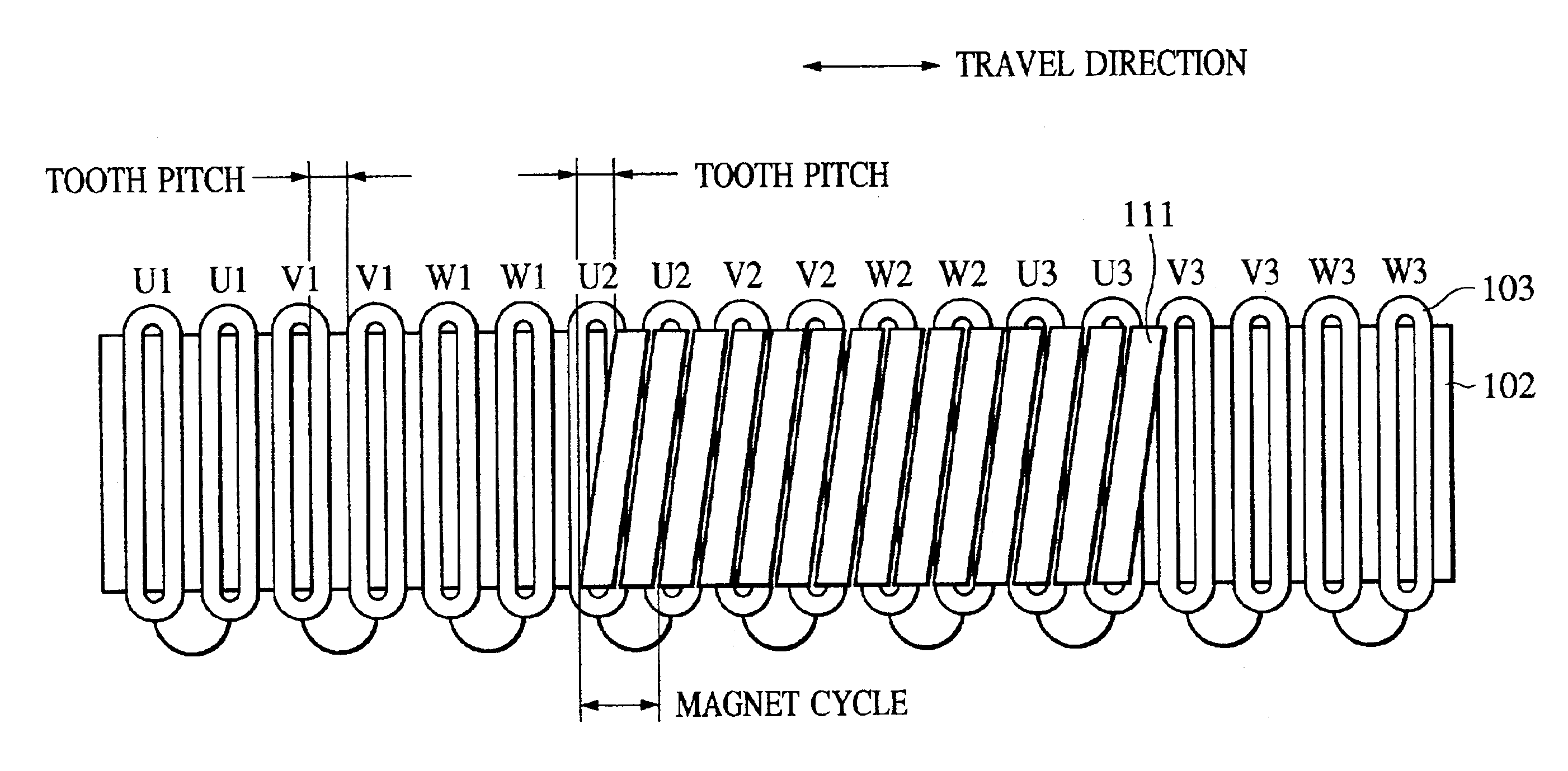
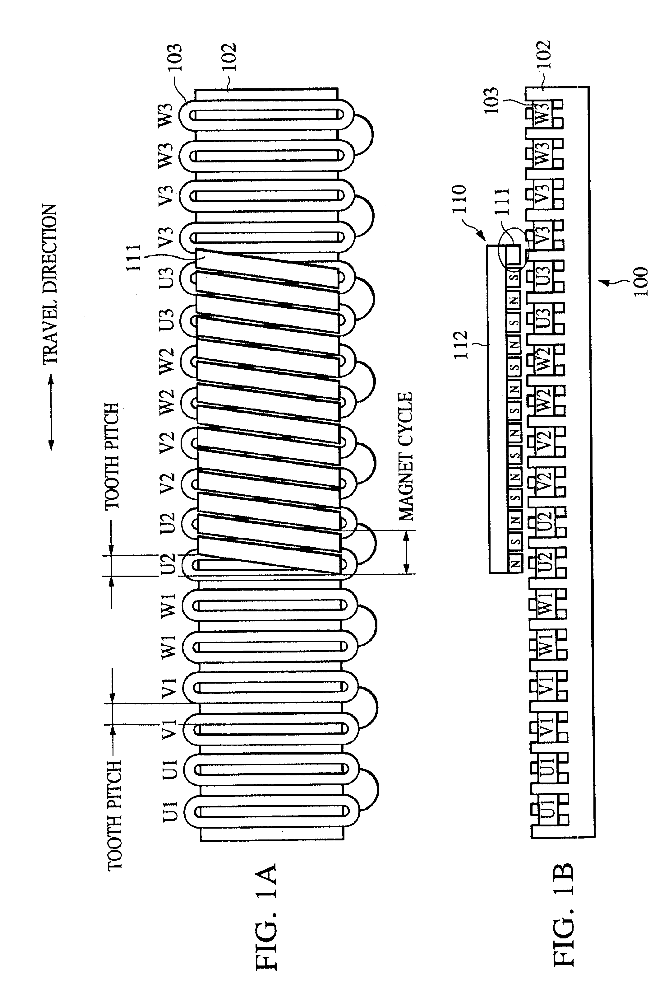
FIGS. 1A and 1B illustrate the structure of a moving-magnet, linear motor according to the present invention, wherein FIG. 1A is a top view illustrating the linear motor in which a back yoke 112 of a mover 110 is removed and the FIG. 1B is a side view of the linear motor.

The linear motor according to the first embodiment has a stator 100 and the mover 110. The stator 100 has a toothed-armature, iron-core 102 with a plurality of teeth and a plurality of coils 103 wound around the teeth of the iron-core 102. The mover 110 has magnet rows formed of a plurality of permanent magnets 111, which are orderly disposed along the traveling direction of the mover 110, i.e., in the thrust direction of the linear motor, and a back yoke 112.

Each permanent magnet 111 forming the corresponding magnet row of the mover 110 has a polygonal shape, such as a parallelogram, a rectangle, and a square and the width thereof extends along the traveling direction of the mover 110. Also, the permanent magnets 1...

second embodiment

FIG. 8 illustrates the configuration of a moving-magnet, linear motor according to the present invention. As shown in FIG. 8, the present invention is also applicable to a linear motor having a structure in which the mover 110 is sandwiched between the two stators 100. In this case, it is preferable to arrange the configuration such that the magnets on the mover 110 facing the upper stator 100 are skewed in a direction opposite to a direction of the magnet on the mover 110 facing the lower stator 100 so that a rotating moment is not exerted on the mover 110.

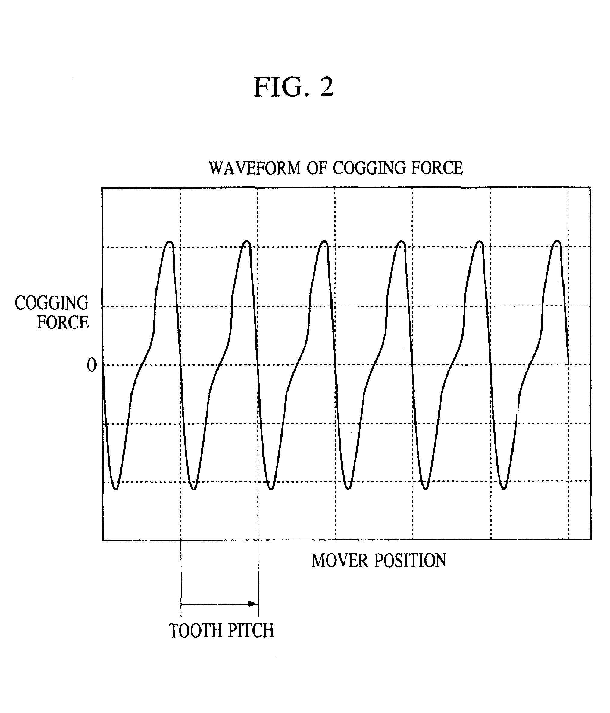
Although the linear motor according to the first embodiment shown in FIGS. 1A and 1B has an 11-pole, 12-slot configuration by way of example, the present invention is also applicable to a configuration having any number of poles and slots. In order to make the cogging force zero and at the same time have a large thrust force, it is desirable to have a large difference in length between the tooth pitch and the magnet cycle.

third embodiment

FIG. 11 illustrates the schematic structure of a scanning aligner according to the present invention. The scanning aligner has at least one stage incorporated therein, which uses the foregoing linear motor, and which serves as at least one of a reticle stage 73 and a wafer stage 93.

The reticle stage 73 is supported by a reticle stage base 71a, which is integrally formed with a frame 94. The wafer stage 93 is supported by a weighing table 92 which has the frame 94 disposed thereon in a standing manner. A linear motor base 71b is supported by a support frame 90, which is directly fixed to a floor F, and which is independent of the weighing table 92. Also, a light source 95 indicated by a dotted line in the figure is prepared so as to produce exposing light by which a reticle pattern on the reticle stage 73 is exposed onto a wafer W on the wafer stage 93.

The frame 94 supports not only the reticle stage base 71a but also a projection optical system 96, which lies between the reticle sta...


PUM

PropertyMeasurementUnit
shapeaaaaaaaaaa
lengthaaaaaaaaaa
widthaaaaaaaaaa

Abstract

A moving-magnet, linear motor which substantially produces no cogging force is provided. The moving-magnet, linear motor has a mover and a stator. The mover has a plurality of permanent magnets orderly disposed along the traveling direction of the mover. The stator has a toothed iron-core having a plurality of teeth and a plurality of coils wound around the teeth thereof. The permanent magnets are disposed such that the two longitudinal ends of each permanent magnet are skewed with respect to each other by a tooth pitch of the toothed iron-core.

Description

1. Field of the InventionThe present invention relates to a moving-magnet, linear motor, an aligner provided therewith, and a method for manufacturing devices, for example, semiconductor devices, using the aligner.2. Description of the Related ArtIn various types of equipment, such as machine tools and semiconductor manufacturing apparatuses, linear motors have been used to achieve accurate positioning control. In machine tools, semiconductor manufacturing apparatuses, and the like, in addition to achieving accurate positioning control, linear motors are required to produce a large thrust force for improving productivity and to have a light-weight mover.FIGS. 9A, 9B, and 9C are a top view, a side view, and an illustration of the configuration of a known moving-magnet, linear motor, respectively, by way of example. The linear motor includes a stator 800 and a mover 810. The stator 800 includes a base 801, a toothed-armature, iron-core 802 (sometimes referred to herein as "toothed iro...

Claims


Application Information

Patent Timeline
Patent Type & Authority Patents(United States)
IPC IPC(8): G03F7/20H02K41/03H01L21/68H01L21/027
CPCG03F7/70758H02K41/031
Inventor KORENAGA, NOBUSHIGE
Owner CANON KK
Why Eureka
Try Eureka