Monolithic battery charging device

a charging device and monolithic technology, applied in the direction of electric variable regulation, process and machine control, instruments, etc., can solve the problems of limiting the design and manufacture of monolithic dc--dc converters with large duty ratios, increasing the package size of dc--dc converters, and inacceptable manufacturing costs

Inactive Publication Date: 2004-09-14
SHAKTI SYST
View PDF7 Cites 50 Cited by
  • Summary
  • Abstract
  • Description
  • Claims
  • Application Information

AI Technical Summary

Problems solved by technology

For instance, a step-down DC--DC converter can provide enough drive current to charge a battery even though the input current may be insufficient to charge the battery load.
Due to operating inefficiency in the duty cycle of the switch, among other things, prior art DC--DC converters use one or more external transformers to achieve large duty ratios, which limit the design and manufacture of monolithic the DC--DC converters having large duty ratios.
Ultimately, these transformers may prevent the design and manufacture of monolithic DC--DC converters having large duty ratios or dramatically increase the package size of the DC--DC converters making manufacture cost unacceptable.
In addition, as noted above, prior art step-down DC--DC converters suffer from having to employ external inductors and capacitors due to many factors, including the resonant frequency of the inductors, capacitor, and battery load.
Known monolithic DC--DC converters, however, suffer from high inductor current, inductor saturation and switch saturation, which result in low efficiency and small duty ratios.
Further, such monolithically formed step-down DC--DC converter should provide small as well as large duty ratios.

Method used


Image

  • Monolithic battery charging device
  • Monolithic battery charging device
  • Monolithic battery charging device

Examples


Embodiment Construction

In the following detailed description, numerous specific details are set forth in order to provide a thorough understanding of the invention. However, it will be understood that the present invention may be practiced without these specific details. In other instances, well-known methods, procedures, components and circuits have not been described in detail, so as not to obscure the present invention. Further, the presently preferred embodiments disclosed are for exemplary purposes only and other embodiments, such as those disclosed in the concurrently filed non-provisional applications entitled (i) "DC--DC Converter with Resonant Gate Drive," (ii) "DC--DC Converter with Current Control," (iii) Synchronous Switched Boost and Buck Converter," and (iv) "DC--DC Converter with Single Gate Drive," may be employed in lieu of or in combination with of the embodiments disclosed.

1. Exemplary Architecture

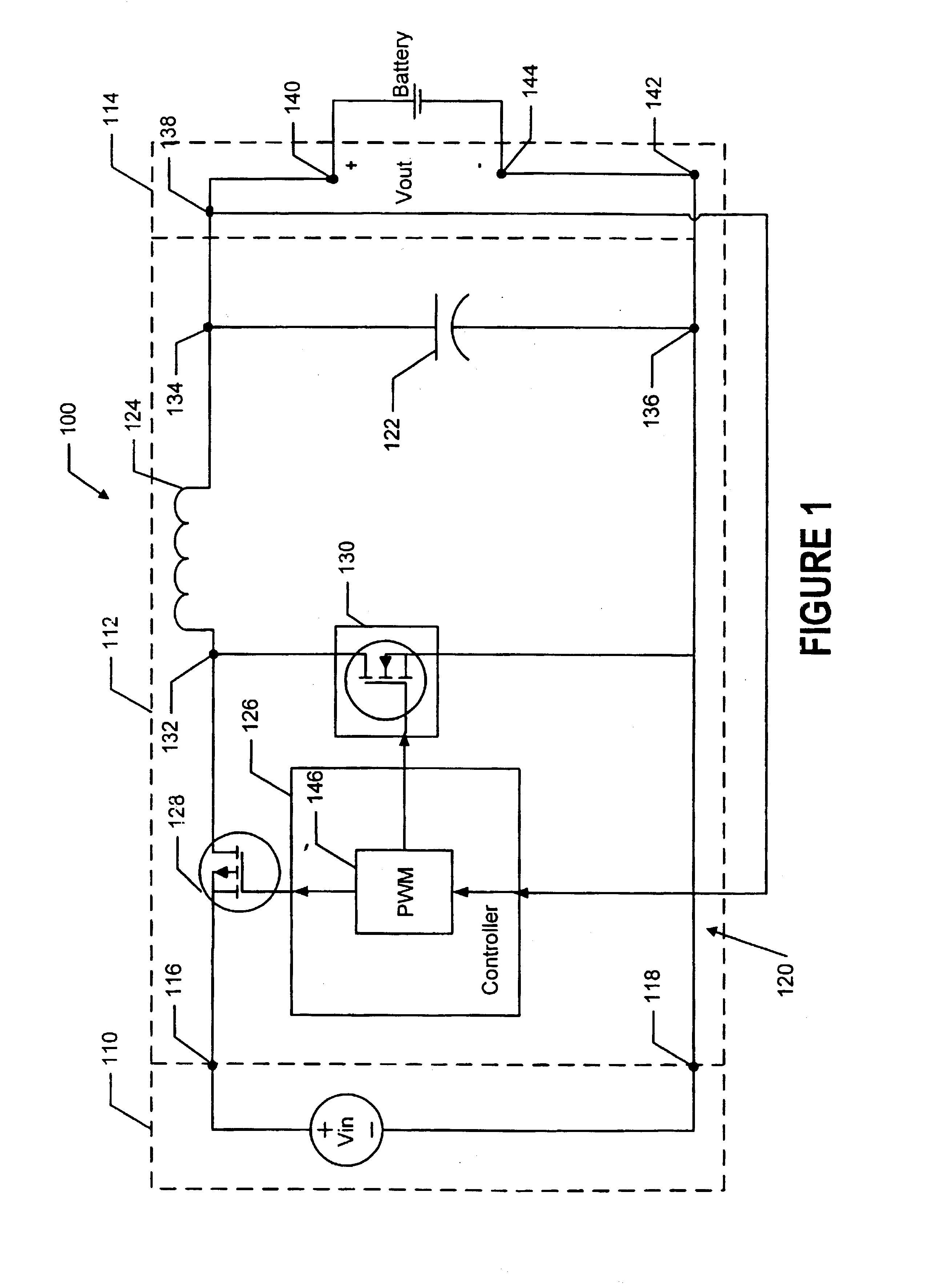
FIG. 1 is a schematic diagram of a monolithic battery charger 100. The battery charger 100...


PUM

PropertyMeasurementUnit
switching frequencyaaaaaaaaaa
frequencyaaaaaaaaaa

Abstract

A monolithically formed battery charger may be fabricated as an integral part of a multifunctional integrated circuit or as independent monolithically formed integrated circuit. The monolithically formed battery charger includes at least one step-down converter having a given duty ratio coupled to a battery-terminal interface that provides a stepped-down output voltage and current that may be used to charge a rechargeable battery.The step-down converter includes one or more cascaded monolithically-formed synchronous-buck regulators operating at a frequency of at least one megahertz. Each regulator may include a capacitor, inductor, controller, switch, and rectifier. When cascaded, the high-side output node of a preceding synchronous-buck regulator is connected to the switch in a successive synchronous-buck regulator.

Description

1. FieldThe field of the invention is related to battery charging devices, and more particularly to monolithically formed battery charging devices having at least one voltage step-down direct-current-to-direct-current converter.2. Related ArtIn general, direct-current-to-direct-current ("DC--DC") converters fall into two categories, namely step-up converters and step-down converters. As the category names imply, a step-up DC--DC converter provides an output voltage that is stepped up from (i.e., greater than) an applied input voltage, and a step-down DC--DC converter provides an output voltage that is stepped down from (i.e., less than) an applied input voltage. Because of the conservation of energy and physical dissipation losses, the current that is output from the DC--DC converter must be less than the input current in the case of step-up converter.Because the voltage output in a step-down DC--DC converter is less than the input voltage, the output current can be greater than the...

Claims


Application Information

Patent Timeline
Patent Type & Authority Patents(United States)
IPC IPC(8): H02J7/00H02M3/158
CPCH02J7/0052H02J7/0055H02M3/1588H02J2007/0059Y02B40/90H02M2001/007Y02B70/1466H02J7/00H02J2207/20H02J2207/40H02M1/007Y02B70/10Y02B40/00
Inventor SHENAI, KRISHNAABEDINPOUR, SIAMAK
Owner SHAKTI SYST
Why Eureka
Try Eureka