Electric wire excess length absorbing device and sliding door-use power feeding apparatus using the same

a technology of absorbing device and power feeding device, which is applied in the direction of cables between relatively moving parts, roofs, doors, etc., can solve the problems of increasing cost and requiring a lot of man-hours for design and manufacturing

Inactive Publication Date: 2004-09-21
YAZAKI CORP
View PDF6 Cites 22 Cited by
  • Summary
  • Abstract
  • Description
  • Claims
  • Application Information

AI Technical Summary

Benefits of technology

As an eighth aspect of the present invention, an electric wire excess length absorbing device comprises: a casing; a reel pivotably provided in the casing for winding an electric wire; and an energizing member to energize the reel in a direction of winding the electric wire, wherein the casing is provided with an opening portion, being long, enabling the electric wire to be swingably led out thereof.
According to the above-described structures of the present invention, the following advantages are provided.

Problems solved by technology

The length of the guide rail 74 or the link arms 72 often has to be changed according to the type of a motor vehicle, which requires a lot of man-hours for the design and manufacturing, thereby increasing the cost.

Method used


Image

  • Electric wire excess length absorbing device and sliding door-use power feeding apparatus using the same
  • Electric wire excess length absorbing device and sliding door-use power feeding apparatus using the same
  • Electric wire excess length absorbing device and sliding door-use power feeding apparatus using the same

Examples


first embodiment

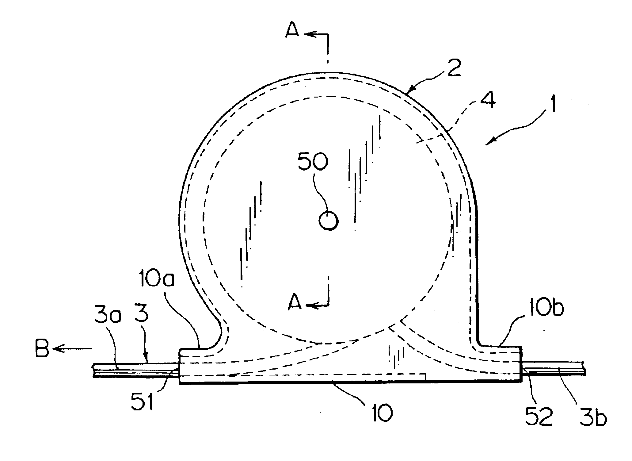
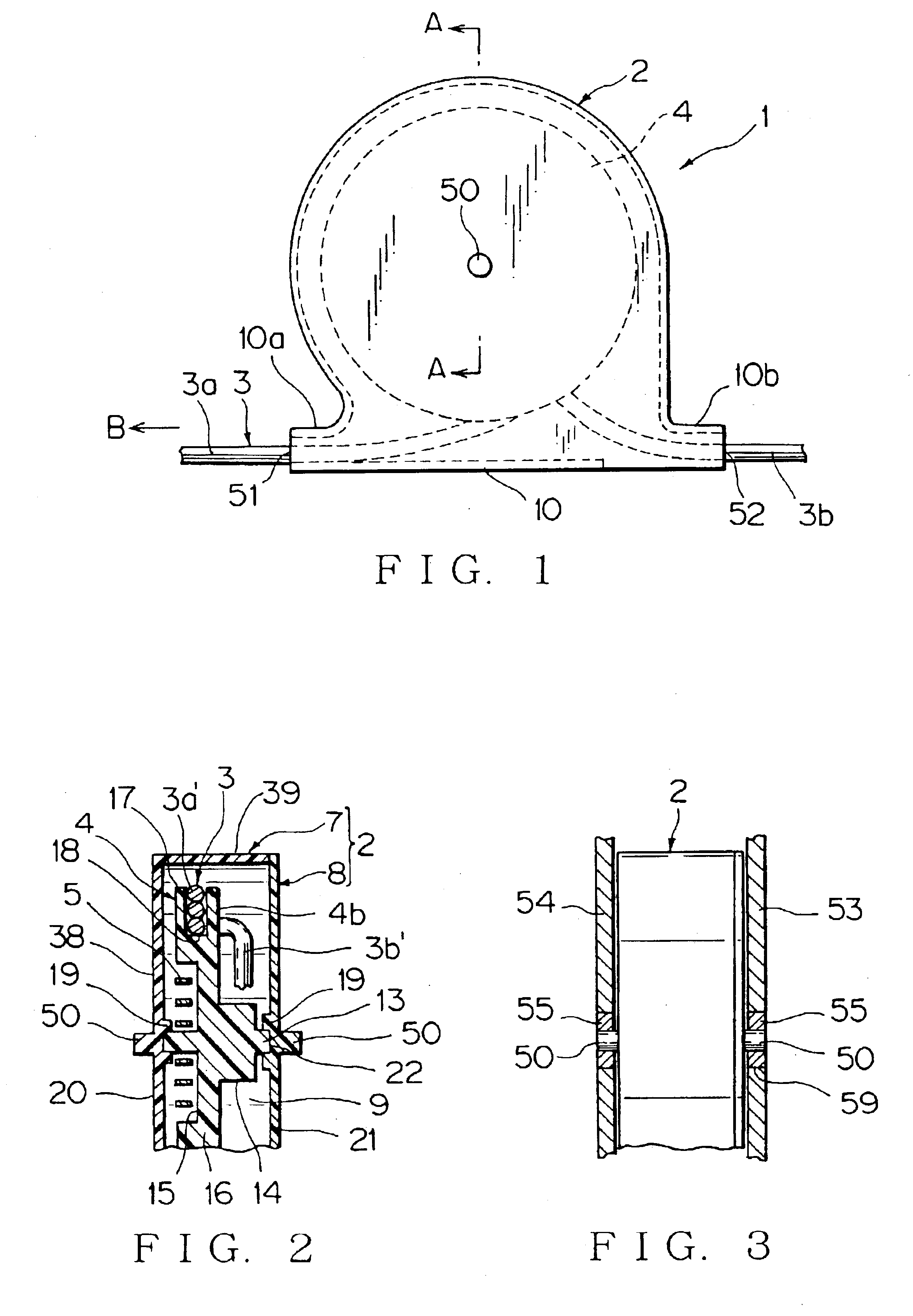
FIG. 1-FIG. 5 show the inventive electric wire excess length absorbing device.

The electric wire excess length absorbing device 1 has a generally cylindrical casing 2 made of synthetic resin, a generally disc-shaped reel 4 made of synthetic resin and pivotably provided in the casing 2 to wind a wiring harness (electric wires) 3, and a spiral spring 5 (FIG. 2, FIG. 4) made of metal to energize the reel 4 in one rotary direction. A rotary shaft 50 projects from each side of the casing 2.

The casing 2 is pivotable on the rotary shafts 50. The casing 2 consists of a first casing body 7 and a second casing body 8 (FIG. 2) and has a reel accommodating portion 9 and a harness leading-out portion 10 (FIG. 1) in a tangential direction of the reel accommodating portion 9. The casing body 7 has a base plate portion 38 and a peripheral wall 39, and the casing body 8 has a base plate portion 21. Both the base plate portions 21,38 are in parallel with each other. The casing bodies 7,8 are fixed to ...

second embodiment

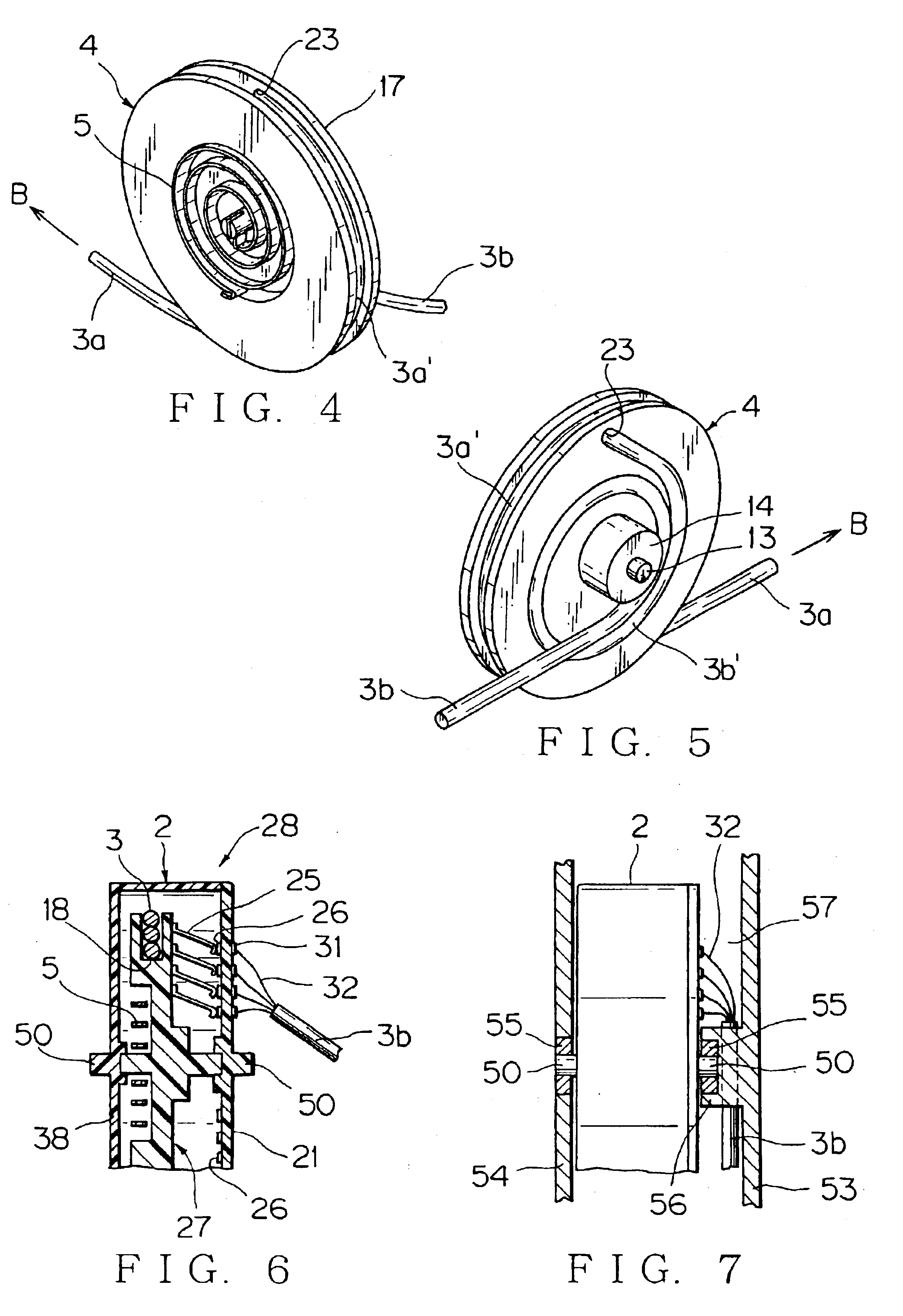
FIG. 6-FIG. 9 show the inventive electric wire excess length absorbing device. In this electric wire excess length absorbing device 28, the loosely wound portion 3b' (FIG. 5) of the previous embodiment is replaced with a contact terminal 25 and an annular circuit conductor 26, which allow the rotation of a reel 27. Since the structure except the contact terminal 25 and the annular circuit conductor 26 is similar to the previous embodiment, the same reference characters are used and detailed description is omitted.

A plurality of contact terminals 25 are provided on a side surface 27b of the reel 27 as shown in FIG. 8, one ends 25a of the contact terminals 25 are connected to the respective electric wires 30 of the moving-side wiring harness 3a. The boss portion 14 (FIG. 2) of the previous embodiment is not necessary on the reel 27. The wiring harness 3 consists of four electric wires 30 in the present embodiment. Each contact terminal 25 connected to the electric wire 30 by means of ...

third embodiment

The action of the electric wire excess length absorbing device 1 of the above third embodiment will be described below with reference to FIG. 26-FIG. 29. One side wall of the opening portion 6 of the casing 2 is outwardly curved, thereby forming a harness guide wall (electric wire guide wall) 34. The moving-side wiring harness 3a led out of the opening portion 6 is connected to a mating wiring harness 36 (FIG. 27) by means of the connector 35.

Referring to FIG. 27, when the mating connecting portion side 37 moves in the arrow D1 direction with respect to the electric wire excess length absorbing device 1, the wiring harness 3a is drawn out of the casing 2 as shown by the arrow B1 against the force of the spiral spring 5 (FIG. 20), and the reel 4 turns as shown by the arrow C1. When the reel 4 is turned, the winding diameter of the loosely wound portion 3b' (FIG. 20) reduces. (The contact terminals 25 of FIG. 23 move integrally with the reel 27 along the circuit conductors 26.) Here, ...


PUM


Abstract

An electric wire excess length absorbing device has a casing, a reel pivotably provided in the casing for winding an electric wire, and an energizing member to energize the reel in a direction to wind the electric wire, which casing has an opening portion to lead out the electric wire. The casing may be formed long between a portion having the reel and the opening portion. A sliding door-use power feeding apparatus has an electric wire excess length absorbing device installed in a sliding door or on a vehicle body. A moving-side electric wire is arranged on one of the sliding door and the vehicle body, and a fixed-side electric wire 3b is arranged on the other of the sliding door and the vehicle body.

Description

1. Field of the InventionThe present invention relates to an electric wire excess length absorbing device to absorb a slack of an electric wire by winding the electric wire on a reel and a sliding door-use power feeding apparatus, of a motor vehicle, using the electric wire excess length absorbing device.2. Description of the Related ArtAn electric wire excess length absorbing device shown in FIG. 42 (Japanese Patent Application Laid-open No. 2000-264136) has been suggested as one of the electric wire excess length absorbing device which releases or retracts an electric wire according to an opening-and-closing of a sliding door of a one-box car or the like.This electric wire excess length absorbing device 71 has a pair of link arms 72, a slider 73 connected to an end of one of the link arms 72, and a guide rail 74 to which an end of the other of the link arms 72 is connected and with which the slider 73 slidably engages.The electric wire excess length absorbing device 71 is arranged...

Claims


Application Information

Patent Timeline
Patent Type & Authority Patents(United States)
IPC IPC(8): B60J5/06B60R16/02H02G11/02H02G11/00
CPCB60J5/06B60R16/0207H02G11/006H02G11/02
Inventor SANO, OSAMUSUZUKI, YASUHIRO
Owner YAZAKI CORP
Why Eureka
Try Eureka