Rear body structure for vehicle body

a rear body and vehicle technology, applied in the direction of roofs, vehicle arrangements, transportation and packaging, etc., can solve the problems of poor no teaching regarding the property of dispersing an external load, and the accompanied problem of floor tunnel reinforcemen

Inactive Publication Date: 2004-10-12
MAZDA MOTOR CORP
View PDF9 Cites 17 Cited by
  • Summary
  • Abstract
  • Description
  • Claims
  • Application Information

AI Technical Summary

Problems solved by technology

That is, the floor tunnel reinforcement is accompanied by a problem of a poor property of dispersing an external load.
However, there is no teaching regarding the property of dispersing an external load in the above mentioned publication.

Method used


Image

  • Rear body structure for vehicle body
  • Rear body structure for vehicle body
  • Rear body structure for vehicle body

Examples


Embodiment Construction

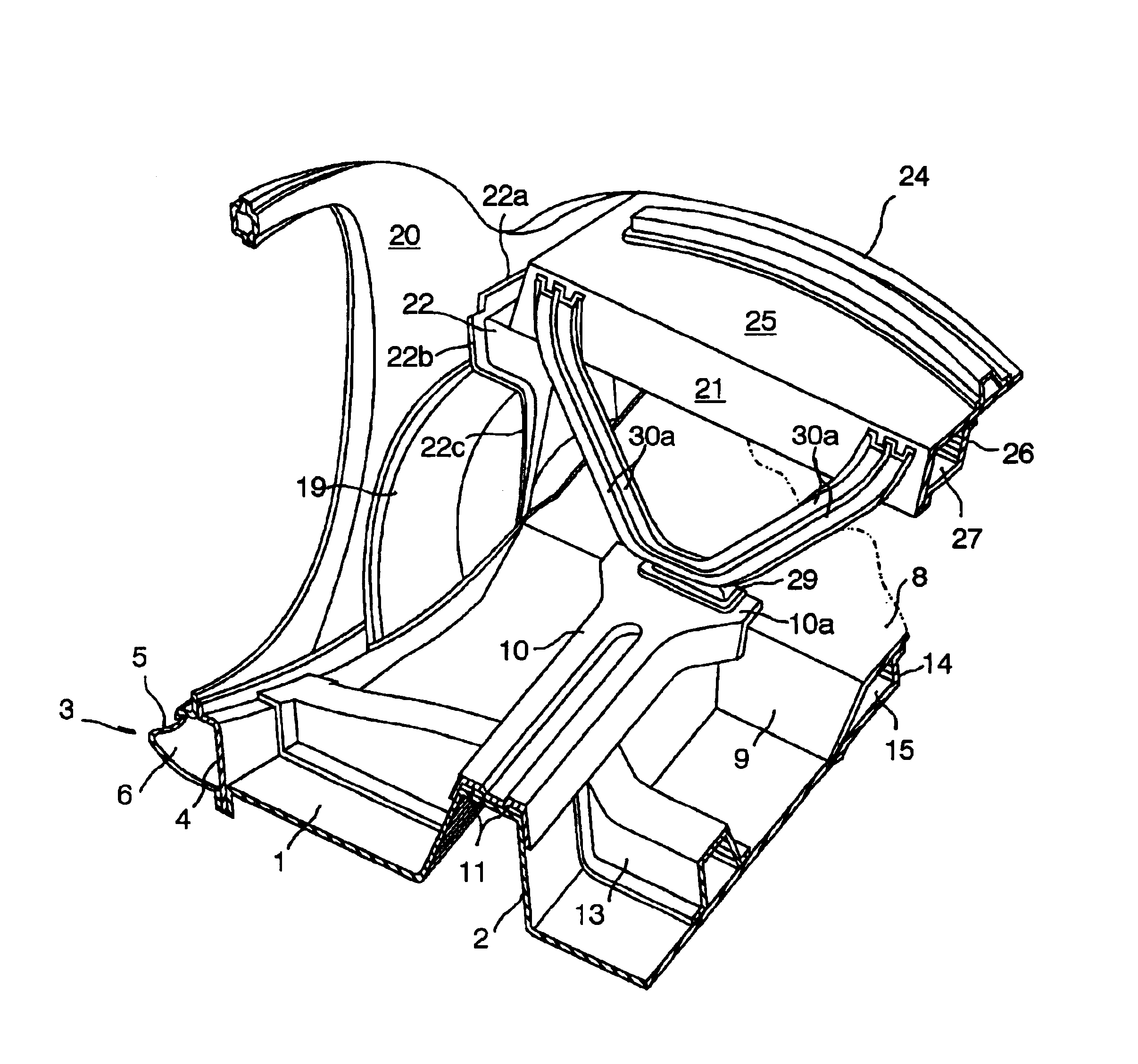
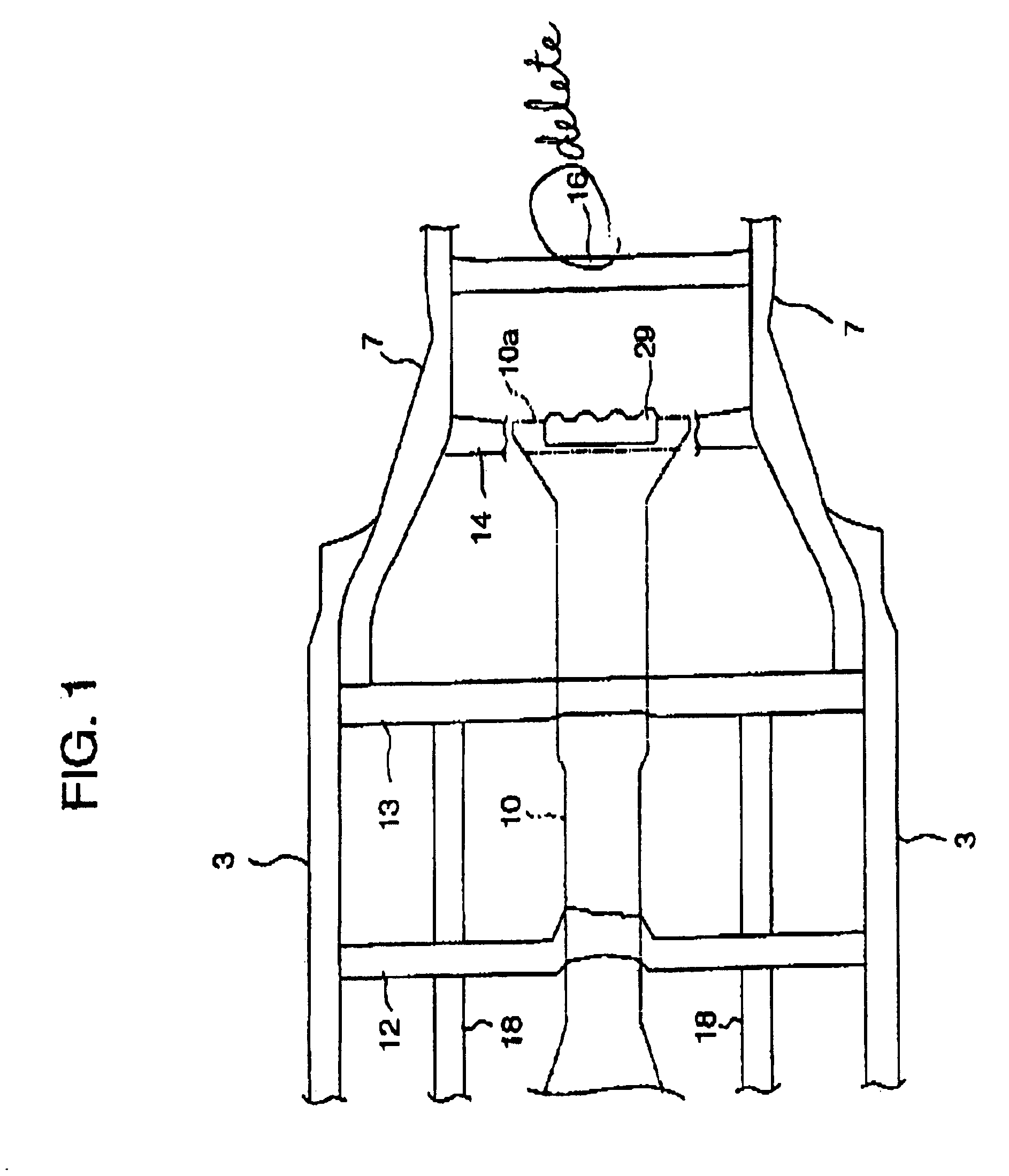
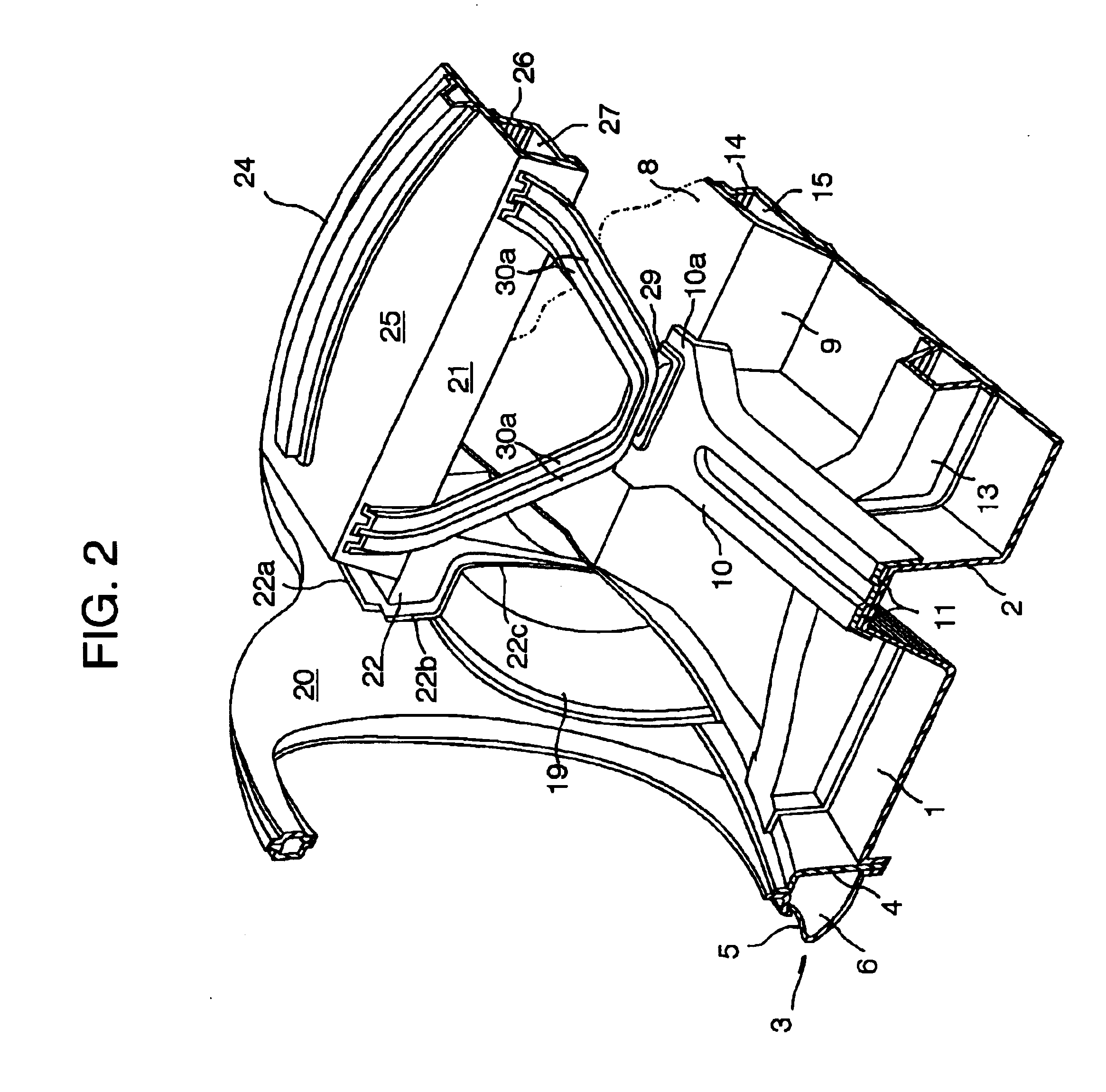
Referring to the drawings in,detail, and, in particular to FIGS. 1 to 3 showing a rear body for a vehicle body according to an embodiment of the present invention, a center floor panel 1 has a convex floor tunnel 2 located in the middle of the floor panel in a transverse direction of a vehicle body and extending in a lengthwise direction from the front to the back of the vehicle body and side sills 3 located at opposite sides of the vehicle body and extending in the lengthwise direction. Each of the side sills 3, that work as rigid structural members of the vehicle body, comprises inner side sill 5 and a outer side sill 5 welded, or otherwise secured, to each other so as to form a closed cross section 6 extending in the lengthwise direction. The rear body includes a rear side frame 7 extending rearward from a rear end portion of the side sill 3 and secured to the center floor panel 1 and a rear floor panel 8 from the under side so as to form a closed cross section between them. The ...


PUM


Abstract

A rear body structure comprises a floor tunnel extending in a lengthwise direction from the front to the back of the vehicle body at a middle of a floor panel in a transverse direction, a floor tunnel reinforcement disposed along the floor tunnel so as to form a closed cross section between them, and a generally V-shaped gusset secured between the floor tunnel reinforcement and a package member interconnecting side walls between which a compartment is formed in the rear body.

Description

1. Field of the InventionThe present invention relates to a rear body structure for a vehicle and, more particularly, to a rear body structure for a rear body structure having a high-mount backbone frame.2. Description of Related ArtThere has been known vehicle bodies having what is called a high-mount backbone frame such as disclosed in, for example, Japanese Unexamined Patent Publication No. 2000-23 8667. The high-mount backbone frame, that is known as a floor tunnel reinforcement a floor tunnel reinforcement disposed on a floor extending in a lengthwise direction of a vehicle body at a central portion of a floor panel and forming a closed cross section between them. This type of floor tunnel reinforcement provides improvement of rigidity of the floor, and hence rigidity of the vehicle body, it is hard for the floor tunnel reinforcement to transmit an external load applied to the floor tunnel reinforcement to an upper body portion of the vehicle body upon an occurrence of a fronta...

Claims


Application Information

Patent Timeline
Patent Type & Authority Patents(United States)
IPC IPC(8): B62D25/08B62D21/00B62D25/20
CPCB62D25/087
Inventor MATSUOKA, HIDENORI
Owner MAZDA MOTOR CORP
Why Eureka
Try Eureka