Antenna structure, method of using antenna structure and communication device

a technology of antenna structure and communication device, applied in the field of antenna structure, can solve the problems of whip antenna, inconvenient whip antenna, antenna burden,

Inactive Publication Date: 2004-10-19
PANASONIC INTELLECTUAL PROPERTY CORP OF AMERICA
View PDF10 Cites 149 Cited by
  • Summary
  • Abstract
  • Description
  • Claims
  • Application Information

AI Technical Summary

Problems solved by technology

However, the whip antenna is inconvenient because it needs to be drawn from the housing when the folding cellular phone is used and needs to be retracted into the housing after use.
And, the whip antenna has a problem in that such drawing and retraction may cause damage thereto.
Thus, the folding cellular phone terminal has problems in that the whip antenna is burdensome because it needs to be drawn and retracted and that the whip antenna is susceptible to damage due to such operations.
Thus, folding portable radio terminals including the folding cellular phone terminal have a problem in that they becomes thick if the internal antenna is used.

Method used


Image

  • Antenna structure, method of using antenna structure and communication device
  • Antenna structure, method of using antenna structure and communication device
  • Antenna structure, method of using antenna structure and communication device

Examples


first embodiment

(First Embodiment)

First, a first embodiment will be described.

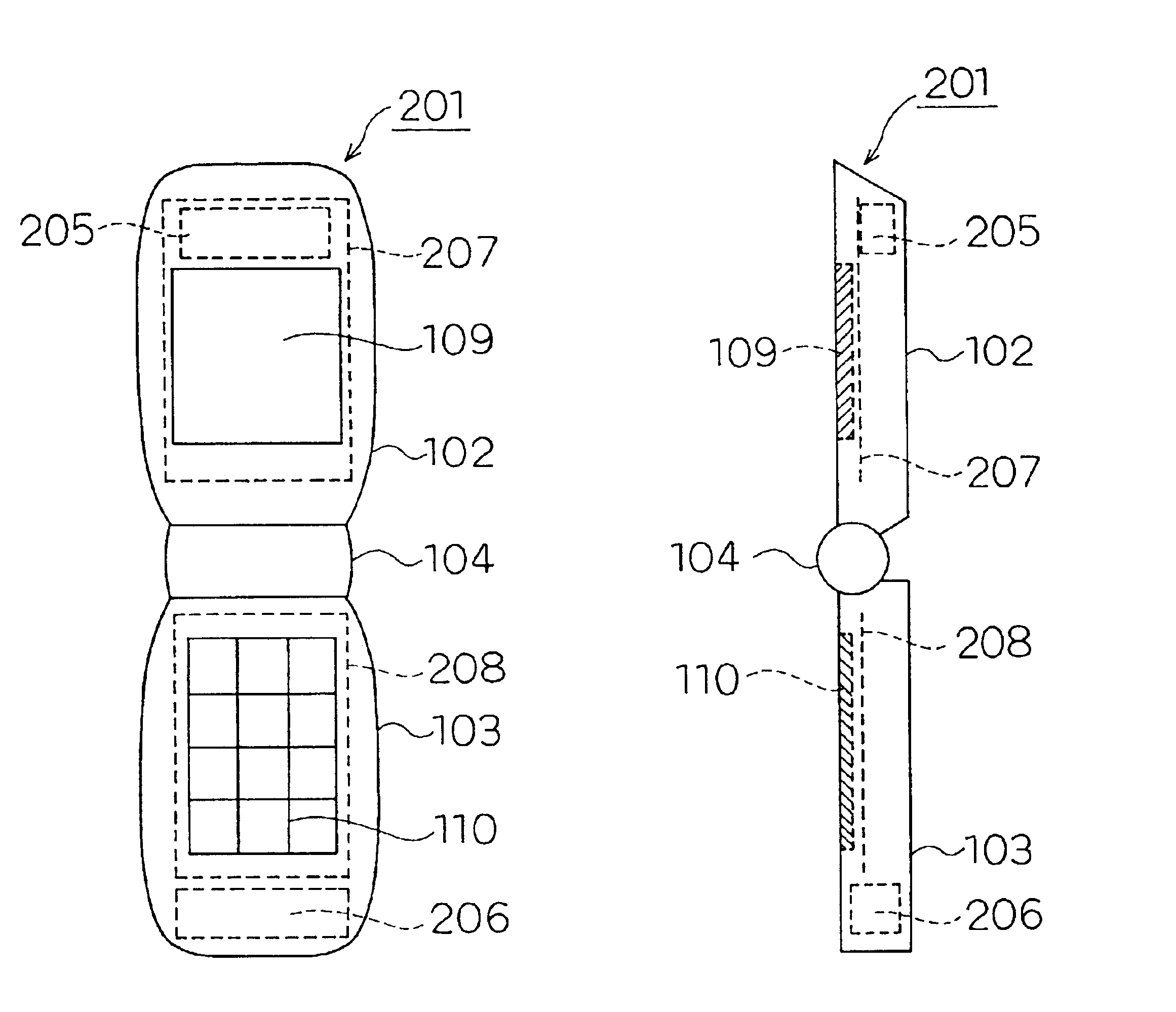
FIGS. 1(a)-(b) show configurations of folding cellular phone terminals 201 according to this embodiment. The folding cellular phone terminal 201 has an internal antenna and includes no whip antenna. FIG. 1(a) is a front view of the folding cellular phone terminal 201, and FIG. 1(b) is a side view thereof.

The folding cellular phone terminal 201 has an upper housing 102 and a lower housing 103 coupled with each other by a hinge part 104, and is configured so that the upper housing 102 can be folded on the lower housing 103 via the hinge part 104. The upper housing 102 and the lower housing 103 are electrically connected to each other via the hinge part 104.

A display 109 is incorporated in the upper housing 102, an upper bottom board 207 is incorporated in the housing at the back side of the display 109, and an upper internal antenna element 205 is incorporated in the housing on a side of the upper bottom board 207 opposite ...

second embodiment

(Second Embodiment)

Now, a second embodiment will be described.

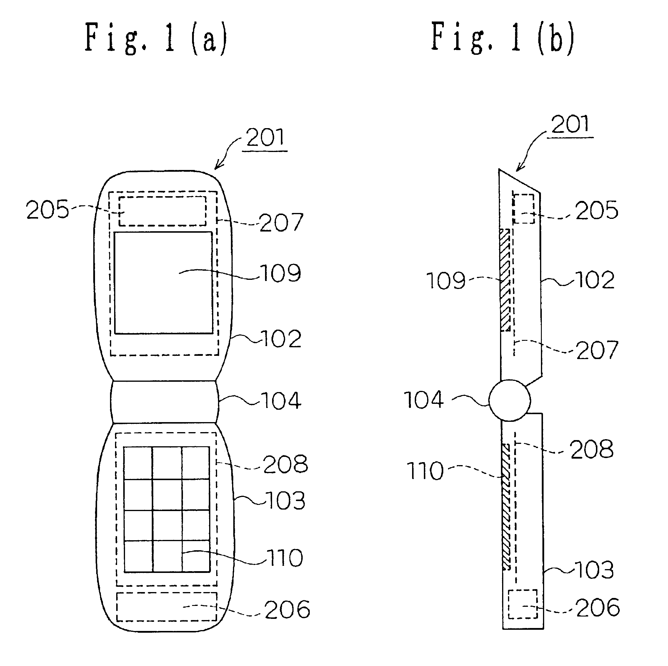
FIGS. 2(a)-2(b) show cellular phone terminals 101 according to this embodiment. FIG. 2(a) is a front view of the cellular phone terminal 101, and FIG. 2(b) is a side view thereof. The cellular phone terminal 101 is of a folding type, and the antenna thereof is only an internal antenna.

The cellular phone terminal 101 has an upper housing 102 and a lower housing 103 coupled with each other by a hinge part 104, and is configured so that the upper housing 102 can be folded on the lower housing 103 via the hinge part 104.

A display 109 is incorporated in the upper housing 102, an upper bottom board 107 is incorporated in the housing at the back side of the display 109, and an upper internal antenna element 105 is incorporated in the housing on a side of the upper bottom board 107 opposite to the display 109. The upper internal antenna element 105, the upper bottom board 107 and a lower bottom board 108 constitute an upper inter...

third embodiment

(Third Embodiment)

Now, a third embodiment will be described.

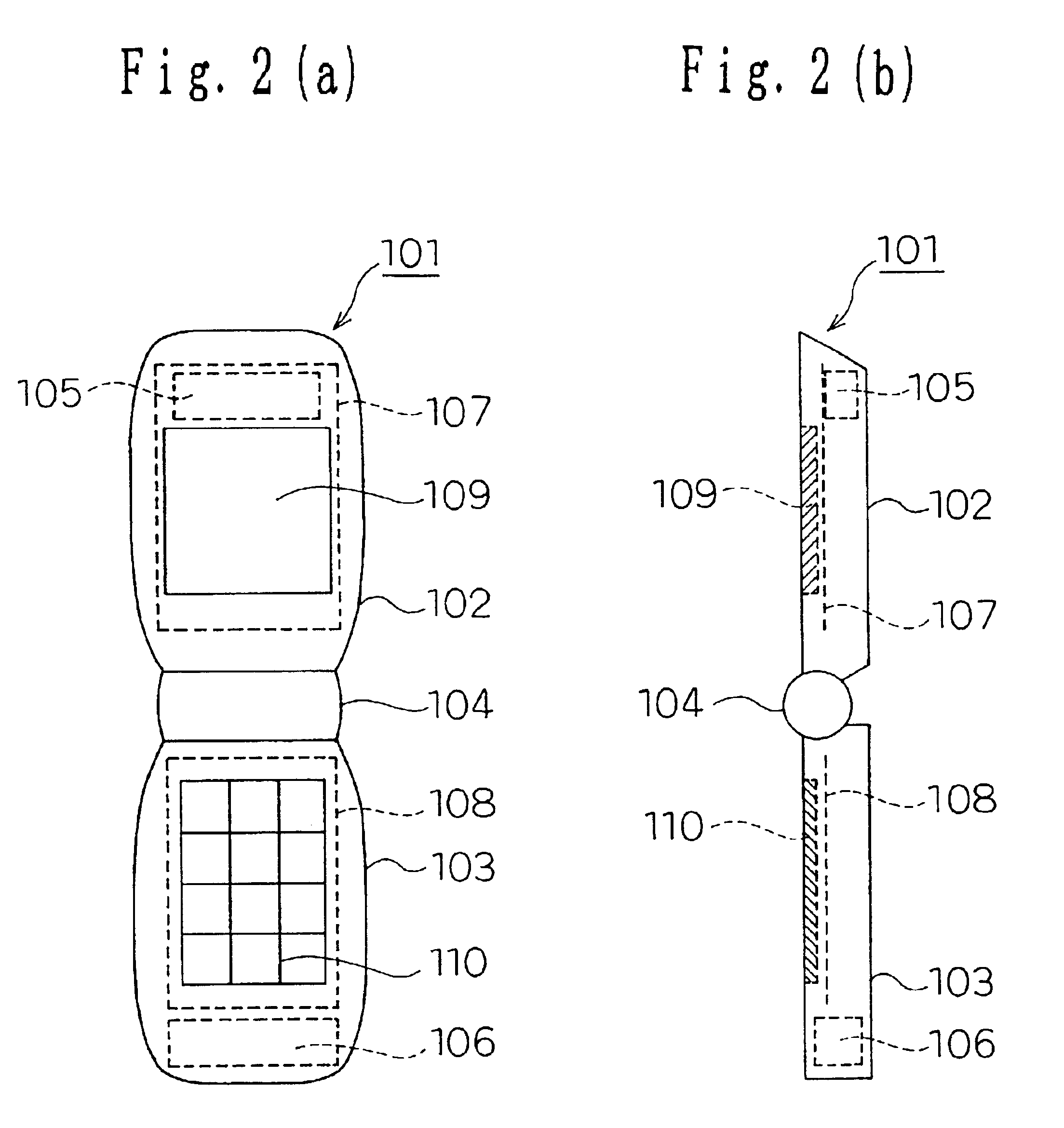
FIG. 2 shows a cellular phone terminal 101 according to this embodiment. The cellular phone terminal 101 according to this embodiment is configured the same as that according to the second embodiment.

A variation from the second embodiment is that the cellular phone terminal 101 according to the third embodiment is of a dual band type that can be used with two frequency bands of 800 MHz-band and 1.5 GHz-band.

Except for this, the third embodiment is the same as the second embodiment.

Now, an operation according to this embodiment will be described primarily with reference to the variation from the second embodiment.

The cellular phone terminal 101 according to the third embodiment carries out radio communication with a base station, not shown, using frequency bands of 800 MHz-band and 1.5 GHz-band.

That is, when the cellular phone terminal 101 is not folded, the upper internal antenna is used both in the 800 MHz-band and 1.5 GHz...


PUM


Abstract

An antenna structure used in a folding portable radio terminal, hasa first antenna; anda second antenna,wherein the first antenna is used at least when the portable radio terminal is not folded, andthe second antenna is used at least when the portable radio terminal is folded.

Description

Field of the InventionThe present invention relates to an antenna structure used in a communication device, such as a folding cellular phone terminal, a method of using the antenna structure and the communication device.Related Art of the InventionDownsizing and slimming of cellular phone terminals are being rapidly advanced. In addition, incorporation of an antenna of a cellular phone terminal into a housing thereof is a world trend.FIG. 19 shows a configuration of an internal antenna of a conventional cellular phone terminal.FIG. 19(a) is a schematic perspective view of the internal antenna of the conventional cellular phone terminal, and FIG. 19(b) is a side view thereof. In FIGS. 19(a) and 19(b), an antenna element 1201 is to send or receive radio wave from the cellular phone terminal or from another cellular phone terminal, and a shielding case 1206 and a radio circuit for communication 1207 housed in the shielding case 1206 are disposed on a substrate 1202. An LCD 1203 is to d...

Claims


Application Information

Patent Timeline
Patent Type & Authority Patents(United States)
IPC IPC(8): H01Q1/24H01Q1/36H01Q21/29H01Q21/00H01Q9/04H01Q1/08
CPCH01Q1/08H01Q1/243H01Q21/29H01Q9/0421H01Q1/362H01Q1/24
Inventor IWAI, HIROSHIYAMAMOTO, ATSUSHIOGAWA, KOICHIYAMADA, KENICHIASAHINA, TOSHIHIROKAMAEGUCHI, SHINJI
Owner PANASONIC INTELLECTUAL PROPERTY CORP OF AMERICA
Why Eureka
Try Eureka