Retractable telescoping fire sprinkler

Inactive Publication Date: 2004-10-26
ANECHOIC SPRINKLER LP
30 Cites 4 Cited by

AI-Extracted Technical Summary

Problems solved by technology

These prior art sprinklers do not disclose a mechanism to retract the sprinkle...

Abstract

A retracting telescoping automatic fire sprinkler is disclosed. In a dry system, the sprinkler extends to its operating position under system pressure that is applied in response to a preaction signal. When system pressure is removed, as in after a test is completed, the sprinkler automatically retracts to its original position.

Application Domain

Operating means/releasing devices for valvesSpray nozzles +1

Technology Topic

Fire sprinklerSystem pressure +1

Image

  • Retractable telescoping fire sprinkler
  • Retractable telescoping fire sprinkler
  • Retractable telescoping fire sprinkler

Examples

  • Experimental program(1)

Example

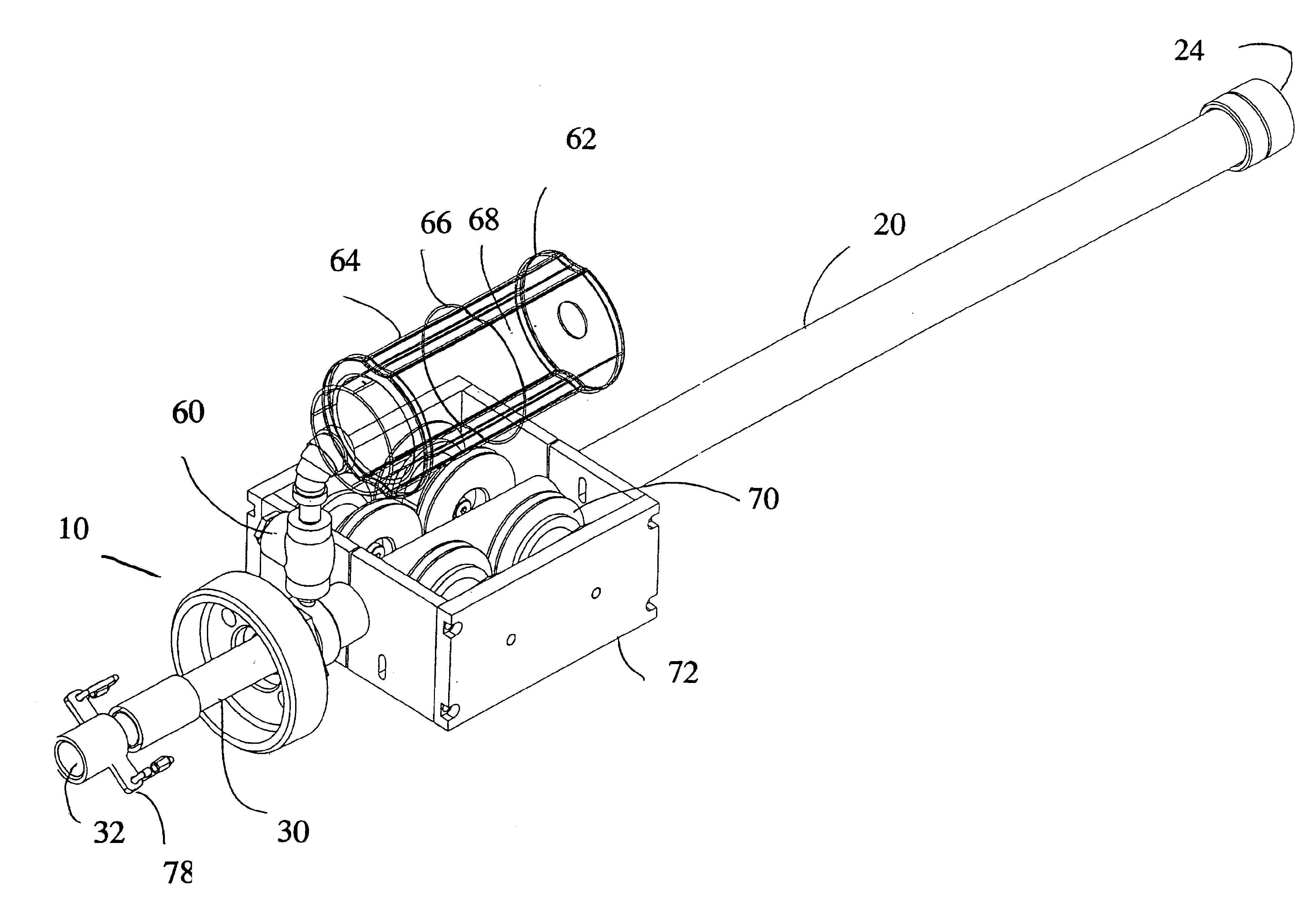
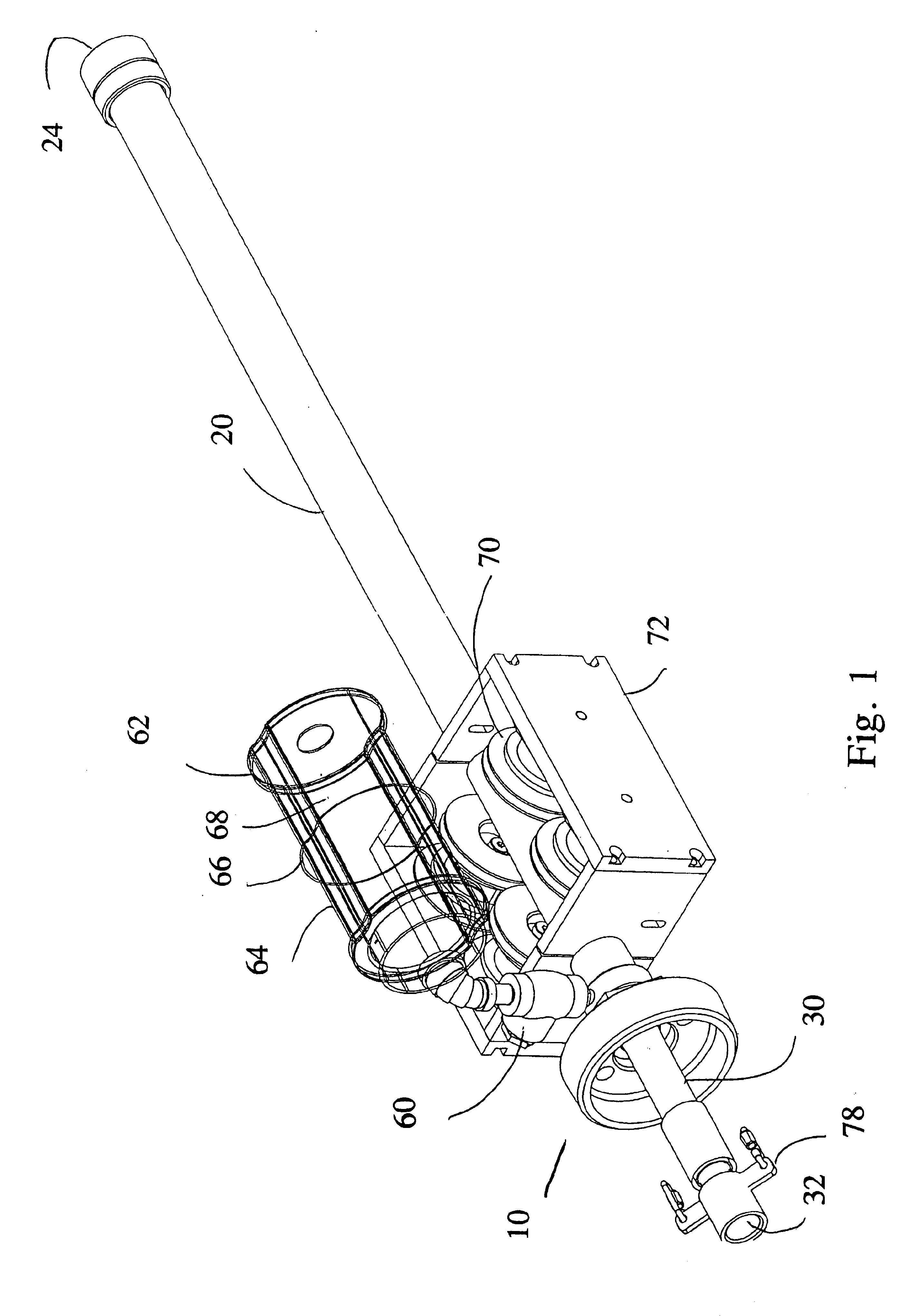
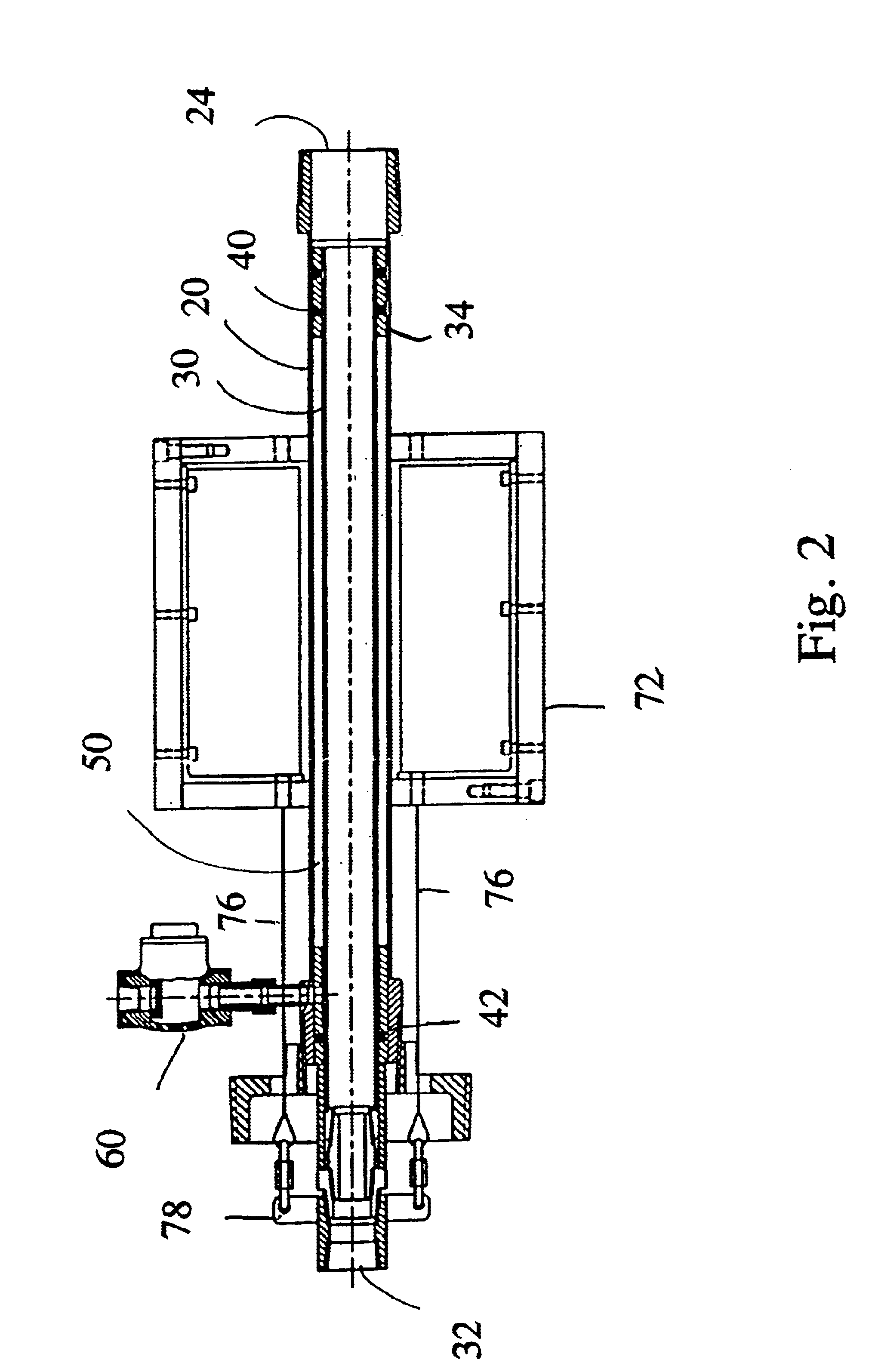
retractable telescoping sprinkler is disclosed. While the sprinkler can be used in any system, the retractable telescoping sprinkler is advantageously used in a dry, preacting sprinkler system. In such a system, the sprinklers are not under pressure, or may be under reduced pressure. In operation, a control systems responding to a sensor detects a condition that requires that the sprinklers be pressurized opens a valve to allow fire extinguishing media--to flow into the sprinklers. Alternatively, if the system has been maintained at some pressure, a sprinkler head may be activated and the control system will deploy the sprinklers in response to the pressure drop. In some cases, the sprinkler heads are open, and fire-extinguishing media can flow from the open heads when the control valve is opened. In other systems, each sprinkler is closed with a thermally sensitive valve. In such a case, the control system will supply fire-extinguishing medium to the sprinkler head under pressure as directed by the control system, but each individual sprinkler will open only in response to heat applied to the sprinkler head.
In FIG. 1, a retractable telescoping sprinkler is shown in the retracted position. The sprinkler 10 includes an outer conduit 20. The outer conduit 20 defines an inner channel 24 that is fluidly connected to an array of pipes capable of supplying fire-extinguishing medium to the sprinkler. The outer conduit 20 is formed from a material suitable for use in an automatic sprinkler system. Such materials are well known to those skilled in the art, and any material suitable for the installation may be used. Examples of materials that may be used include stainless steel, steel, copper, chlorinated polyvinyl chloride, and polybutylene. The channel 24 in outer conduit 20 should be sized to allow inner conduit 30 to slide longitudinally within channel 24. The outer conduit includes fitting adapted to be connected to a supply of fire extinguishing agent at one end and a stop 22 at one end. This stop is composed of a fire resistant material and is securely attached to the outer conduit. The stop can be a weldment, a threaded bushing, or secured by any means that will form a secure attachment between stop 22 and the outer conduit 20.
The sprinkler 10 includes an inner conduit 30. The inner conduit is sized such that it can move longitudinally within the channel 24 of outer conduit 20. The inner conduit is formed from materials suitable for use in an automatic fire sprinkler system and compatible with the materials used in the outer conduit and the particular characteristics of the installation. Inner conduit 30 defines an inner channel 32 that is fluidly connected to the channel 24 of the outer conduit. Inner conduit 30 is of a size sufficient flow of fire extinguishing medium to the sprinkler head at operating pressures. Inner conduit 30 includes a stop 34 at one end. The stop 34 extends axially from the outer walls of the inner conduit 34 toward the inner walls of the outer conduit. Inner conduit 30 also includes an opening at the other end. This opening is adapted to connect to a sprinkler head, or other fluid connector.
The stop 22 of the outer conduit defines an opening 26 such that the inner conduit may slide longitudinally through said passage 26, but stop 34 will but against stop 22, or a sleeve 31, in the extended position preventing the inner conduit 30 from sliding out of the outer conduit 20 when the sprinkler is extended. Inner conduit 30 acts as a piston within outer conduit 20. Outer conduit 20 serves as a cylinder for inner conduit 30. In one embodiment, stop 22 of the outer conduit 20 is a nipple formed from 300 series stainless steel. The nipple defines a central opening having a diameter of slightly larger than the outer diameter of the inner conduit. One end of the nipple is adapted to be secured to the outer conduit. A channel 38 is provided through nipple 22. The channel 38 can conveniently be threaded to receive the flow control valve. A groove can be machined on the inner wall of the nipple below the to accept an O-ring.
A sleeve 31 may be disposed within the space between inner conduit 30 and outer conduit 20, sealingly engaging the surfaces of the conduit. Optionally, the sleeve may be positioned proximate stop 22. An additional sleeve may be used as a journal bearing on the inner conduit 30. The sleeve may be made of any suitable material. Vespel.RTM. polyimide, a product of DuPont has been used.
Inner conduit 30 has is positioned such that stop 34 is positioned within the channel of the outer conduit 20 and the length of inner conduit 30 extends through the opening 26 in stop 22. The inner conduit 30 can be of any convenient length to permit the sprinkler head to come into proper position when telescoped. The outer conduit 20 has a length that permits the inner conduit 30 to retract into the chamber of the outer conduit.
Sealing means 40, 42 are located to define a chamber 50 between the inner conduit 30 and the outer conduit 20. If outer conduit 20 and inner conduit 30 are tubes, chamber 50 is annular. The seals slidably engage the walls of the conduits and define a closed volume. One seal means 40 is positioned near stop 22 of inner conduit 30. Another seal means 42 is positioned proximate around the periphery of inner conduit 30 proximate stop 34. These seals may conveniently be O-rings. A plurality of O-rings may be used at each end of the chamber. O-rings of any material may be used. Buna-N, Viton, and neoprene O-rings have been used.
The inner walls of outer conduit 20, the outer walls of inner conduit 30, and the sealing means 40 and 42 define chamber 50. When the inner conduit 30 is nested in the outer conduit 20, chamber 50 has defined volume Seal 40 engages the outer periphery of the inner conduit 30 and the inner surface of outer conduit 20. As the inner conduit 30 extends, Seal 40 slides along the inner surface of outer conduit 20 and seal 42 engages the periphery of inner conduit 30 as it slides out of the outer conduit.
Chamber 50 can be fluidly connected to a flow control valve 60 through opening 38. Opening 38 is a threaded opening in the wall of outer conduit 20 or through the side of stop. Valve 60 is in fluid communication with the space 24. The valve permits fluid to flow out of chamber 50 at a rate that can be adjusted by an operator. Additionally valve 24 permits fluid to flow into the chamber 50. By varying the size of the orifice 61 in the valve in combination with the liquid in the chamber 24. Any fluid can be used in the chamber. Preferably the fluid is an incompressible liquid. Solutions of water and glycerine, containing from about 0.01 to about 80 percent glycerine (by volume) have been useful. An orifice with a diameter of 1/8 inch, used with a 50% glycerine in water solution resulted in retraction times of about 10 seconds.
Flow control valve 60 can be fluidly connected to reservoir 64. One reservoir 64 may be connected to one or many fluid control valves. Reservoir 64 should have a sufficient capacity to hold the volume of fluid in all chamber 50 to which it is fluidly connected. Reservoir 64 may be a fluid expansion tank such as the type commonly used in recirculating hot water systems. Such a system may include a diaphragm 66 defining two chambers 62, 68 within the reservoir. The first chamber 62 is fluidly connected to the flow control valve 60. The second chamber 68 is separated from the first chamber by a flexible membrane 66 and contains a gas under some pressure. The second chamber may be connected to a vent or gas under pressure.
One embodiment of the sprinkler includes a one or more springs 70 secured to anchoring brackets 72. The anchoring brackets may be mounted on outer conduit 20. Springs 70 can be mechanically connected to a bracket 78 attached proximate the distal end of inner conduit 30. The bracket 78 can be conveniently attached to a modified coupling that couples the inner conduit 30 to the sprinkler head. Advantageously, the coupling will be above the deflector of the sprinkler head, and will not interfere with the distribution of water from the sprinkler. The spring can be balanced to maintain inner conduit 30 in a retracted position. Two springs may be used to provide approximately equal tension on both sides of the inner conduit to ensure that the tension of the springs is evenly applied. The springs 70 are preferably torsion springs. One way the springs can be connected to the distal end of the inner conduit 30 is by a cable 76 of appropriate mechanical strength and temperature resistance. Because in use cable 76 may be exposed to fire conditions, it should be made from materials that meet applicable standards for the fire hazard in the area where the sprinkler is deployed.
In operation, the retractable telescoping sprinklers are positioned in an array such that the spray pattern from the sprinkler heads when one or more sprinkler heads are activated will deliver the required distribution of fire extinguishing media to the area being protected. In an anechoic echo chamber, typical spacing might be one sprinkler head for each 90 feet of floor area. Depending on the fire hazard, the sprinklers could be positioned to with higher or lower densities as is understood in the art.
Depending upon the fire hazard of the area being protected, the ceiling height, and other factors known to those skilled in the art, a fire sprinkler system is sized to deliver a specified density of water delivery. In areas of light hazard, a flow density of from about 0.1 to about 0.2 gallons of water/square foot/minute may be adequate. In areas with higher fire hazards, higher flow rates of from about 0.2 to about 2.0 gallons/square foot/minute may be specified. Sprinkler heads with different distribution patterns and coverage areas may be used. If necessary, a shield to protect a sprinkler head from spray from an adjacent sprinkler head may be used. Water supply static pressure, flow, and residual pressure must be considered when sizing the sprinkler system. Of course following known guidelines for sprinkler system placement, sprinklers when deployed should have an unobstructed spray pattern. Positioning the top surface of the deflector between about 4 and about 12 inches lower than any obstruction to the spray pattern generally provides acceptable water distribution. For example, systems with a static pressure of about 90 psi, and a residual pressure of about 50 psi at a flow of about 100 gpm can adequately supply a retractable sprinkler system for an area rated for NFPA ordinary hazard of about 3000 sq. ft.
When the system is installed, the each retractable, telescoping sprinkler is connected to a matrix of supply pipes. The pipes are connected to a preaction valve and a control system. The control system includes smoke detectors, heat detectors, manual pull stations, and valves, switches, indicators, annunciators, alarms, and controls. One typical system is sold under the trade name Pyrotronics System XL 3. Each telescoping retracting sprinkler is installed in its retracted position. A suitable cover can be placed over the mounting flange to conceal the sprinkler. When a fire condition is detected, or in response to manual pull station or test signal, the preaction valve opens and water or an appropriate fire fighting media flows into the matrix of supply pipes. The water entering the pipes has a pressure that exerts a force on the inner conduit 30 pressing the inner conduit 30 to extend to the deployed position. When the inner conduit is extending, the fluid contained in space 24 between inner conduit 30 and outer conduit 20 flows through control valve 60 into reservoir 62. While inner conduit is extending, cables 76 attached to brackets 78 are in tension. As the cables are pulled, springs 70 apply a force to prevent the retractable sprinkler from slamming into the extended position. When the sprinkler system is full, and the retractable sprinklers have reached their stable extended positions, the pressure in the system returns to the static pressure. In a fire condition, one or more of the sprinkler heads may open in response to an elevated temperature. When the sprinkler is discharging, the residual pressure of the water supply is preferable sufficient to keep the sprinklers in a fully extended position.
When the water supply to the sprinklers is interrupted, the springs 70 attached to the brackets 78 by cables 76 retract and pull the inner conduit 30 sprinkler back to the retracted position within outer conduit 20. When the inner conduit retracts, fluid flows from reservoir 62 through control valve 60 into the space 24 between the inner conduit 30 and the outer conduit 20.

PUM

no PUM

Description & Claims & Application Information

We can also present the details of the Description, Claims and Application information to help users get a comprehensive understanding of the technical details of the patent, such as background art, summary of invention, brief description of drawings, description of embodiments, and other original content. On the other hand, users can also determine the specific scope of protection of the technology through the list of claims; as well as understand the changes in the life cycle of the technology with the presentation of the patent timeline. Login to view more.
Why Eureka
Try Eureka