Fire sprinkler with flue-penetrating non-circular spray pattern

a fire sprinkler and spray pattern technology, applied in the field of fire sprinklers, can solve the problems of increasing the cost of an installed fire suppression system, affecting the safety of personnel, so as to reduce the number of supply lines, reduce the volume, and reduce the effect of pressure and volum

Active Publication Date: 2016-07-05
FIREBIRD SPRINKLER COMPANY
View PDF48 Cites 18 Cited by
  • Summary
  • Abstract
  • Description
  • Claims
  • Application Information

AI Technical Summary

Benefits of technology

[0013]According to another aspect of this invention. A fire sprinkler assembly of the type for dispersing a fire suppressing liquid over a non-circular coverage area is provided. The assembly comprises a frame. The frame includes a fastener configured to connect with a supply line so as to receive an outflow of fire-suppressing liquid from the supply line along an outflow axis. A deflector is supported by the frame and configured to disperse the outflow of fire-suppressing liquid in a generally non-circular conical downward spray to achieve a non-circular coverage area below the fire sprinkler assembly. The deflector has an overall width. And a longer overall length that is proportioned so that the resulting minor diameter is between about 15% and 67% of the major diameter. A mid-point of the deflector is generally centered on the outflow axis. The deflector comprises a generally semi-cylindrical body disposed perpendicularly to the outflow axis and is effective to evenly disperse the outflow of fire-suppressing liquid over the non-circular coverage area.
[0015]This invention provides an improved fire sprinkler that is capable of operating with fewer supply lines than was possible using prior art techniques. Even operating through fewer supply lines, the improved fire sprinkler may be effectively operated with less pressure and volume depending on final storage occupancy. This improved fire sprinkler has the capability to produce larger water droplet sizes and / or increased water discharge velocity. The fire suppression system of this invention can be implemented so as to deliver the maximum available amounts of water (or other fire suppressing liquid) onto a fire. And still further, this invention is uniquely designed to combat fires in warehouse settings where storage items are tightly stacked or arranged and water from activated fire sprinklers must travel into narrow flues to reach a fire.

Problems solved by technology

When fire sprinklers are located close to each other, the risk of “cold soldering” becomes a concern.
However, addressing these factors has been limited by the constraint of available supply line.
Simply designing a prior art spray head so that it is capable of discharging at a greater velocity, or that possesses a higher k-factor, or produces larger droplet sizes is not an option because each increased aspect will require higher supply line pressure and / or larger diameter supply line piping—both of which substantially increase the cost of an installed fire suppression system.
An unchecked fire can quickly destroy storage items either by direct combustion, or collaterally be heat, smoke or water.
Furthermore, storage items stacked or arranged in long rows often offer an abundant fuel source for a fire to grow and quickly propagate, making it that much more difficult to extinguish the fire.
This objective is often frustrated in warehouse storage settings due to the fact that stacked or arranged rows of storage items tend to make it difficult for the water spray to reach an interior fire.
When a fire originates between two rows of storage items, particularly when they are arranged back-to-back (i.e., with a longitudinal flue in between), it is very difficult to reach the fire with water dispersed from a fire sprinkler.

Method used


Image

  • Fire sprinkler with flue-penetrating non-circular spray pattern
  • Fire sprinkler with flue-penetrating non-circular spray pattern
  • Fire sprinkler with flue-penetrating non-circular spray pattern

Examples


example 1

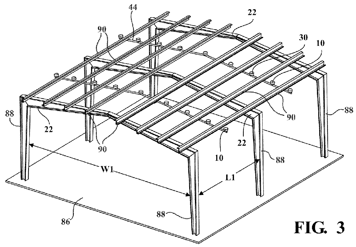
[0081]A sprinkler head 42 has a coverage area 28 with a twenty-five foot major diameter (L2) and an eight foot minor diameter (W2). The k-factor is k=17. At a steady 52 psi line pressure, this sprinkler head 42 will distribute approximately 122.58 gpm.

example 2

[0082]A sprinkler head 42 has a coverage area 28 with a twenty-five foot major diameter (L2) and a four foot minor diameter (W2). The k-factor is k=11. At a steady 35 psi line pressure, this sprinkler head 42 will distribute approximately 65.07 gpm.

[0083]In Example 1, it may be presumed that only one fire sprinkler 42 will activate because of the greater spacing (six-to-eight feet) between adjacent spray heads 42. This single activated spray head 42, fed by 52 psi line pressure, will deliver approximately 122.58 gpm onto the fire. However, in Example 2, it may be presumed that two fire sprinklers 42 will concurrently activate because of the closer spacing (four-to-five feet) between adjacent spray heads 42. These two activated spray heads 42, fed by a modest 35 psi line pressure, will combine deliver approximately 130.15 gpm onto the fire. Thus, two spray heads 42 operating at lower supply line 44 pressure can deliver water at a greater rate onto a fire than can a single spray head ...


PUM


Abstract

A fire sprinkler of the preferred embodiments includes a frame, a trigger, and a deflector. The frame defines a duct to exhaust the flow of a fire suppressing or extinguishing substance, and includes a fastener to fasten the frame to a supply line. The trigger blocks the flow of the fire suppressing or extinguishing substance through the duct during a first mode, and permits the flow of the fire suppressing or extinguishing substance during a second mode. The deflector redirects the flow of the fire suppressing or extinguishing substance into a coverage area. The deflector also at least partially shields the trigger from the dispersal of a fire suppressing or extinguishing substance from an adjacent fire sprinkler and prevents a failure of the trigger.

Description

CROSS REFERENCE TO RELATED APPLICATIONS[0001]This application is a continuation-in-part of U.S. Publication No. 2014 / 0083722, which is a continuation of U.S. Pat. No. 8,602,118, which is a continuation-in-part of international patent application number PCT / US2006 / 025278, all of which are incorporated in their entirety by this reference.[0002]This application is also related to international patent application number PCT / US2006 / 025111, filed on 27 Jun. 2006, and entitled “Fire Sprinkler System and Method of Installation”, which is incorporated in its entirety by this reference.BACKGROUND OF THE INVENTION[0003]1. Field of the Invention[0004]The invention relates generally to the fire suppression and extinguishment field, and more specifically to a new and improved fire sprinkler in the fire suppression and extinguishment field.[0005]2. Description of Related Art[0006]Fire sprinkler systems have been used in the United States to protect warehouses and factories for over one hundred yea...

Claims


Application Information

Patent Timeline
Patent Type & Authority Patents(United States)
IPC IPC(8): A62C3/00A62C37/14A62C35/68
CPCA62C3/002A62C35/68A62C37/14B05B1/267
Inventor PIGEON, JEFFREY J.
Owner FIREBIRD SPRINKLER COMPANY
Why Eureka
Try Eureka