System for identifying defects in a composite structure

a composite structure and defect detection technology, applied in the field of composite structure fabrication, can solve the problems of slowed manufacturing process, false readings in each system, and inability to accurately identify defects in the contour/curved regions of workpieces, so as to save time, labor and money, accurate identification of workpiece defects

Inactive Publication Date: 2005-03-29
THE BOEING CO
View PDF34 Cites 105 Cited by
  • Summary
  • Abstract
  • Description
  • Claims
  • Application Information

AI Technical Summary

Benefits of technology

The systems for identifying defects in a composite structure of the present invention are capable of identifying defects in all areas of a workpiece, even the contoured/curved regions of the workpiece, by more adequately illuminating the surface of the workpiece. In this regard, the system provides ample light and disperses the light over a sufficiently large area of the workpiece such that all of the surfaces of the workpiece, including the contoured/curved surfaces that face away from the light, are adequately

Problems solved by technology

However, the fabrication process has been disadvantageously slowed by the inspection process.
However, this system provides only a single reference point when inspecting workpieces that cannot be modified by the operator.
However, this system also requires that the standard measurements are preloaded into the computer and not controllable by the operator thereafter.
Each of these systems, however, is susceptible to obtaining false readings due to glare or other problems caused by ambient lighting or by the laser-based scanning system.
In particular, the systems do not provide accurate identification of defects in the contoured/curved regions of workpieces.
In this regard, conventional machine-based inspection systems lack suitable lighting to provide the high contrast that is necessary to locate defects on all areas of the workpiece, while preventing ambi

Method used


Image

  • System for identifying defects in a composite structure
  • System for identifying defects in a composite structure
  • System for identifying defects in a composite structure

Examples


Embodiment Construction

The present invention now will be described more fully hereinafter with reference to the accompanying drawings, in which preferred embodiments of the invention are shown. This invention may, however, be embodied in many different forms and should not be construed as limited to the embodiments set forth herein; rather, these embodiments are provided so that this disclosure will be thorough and complete, and will fully convey the scope of the invention to those skilled in the art. Like numbers refer to like elements throughout.

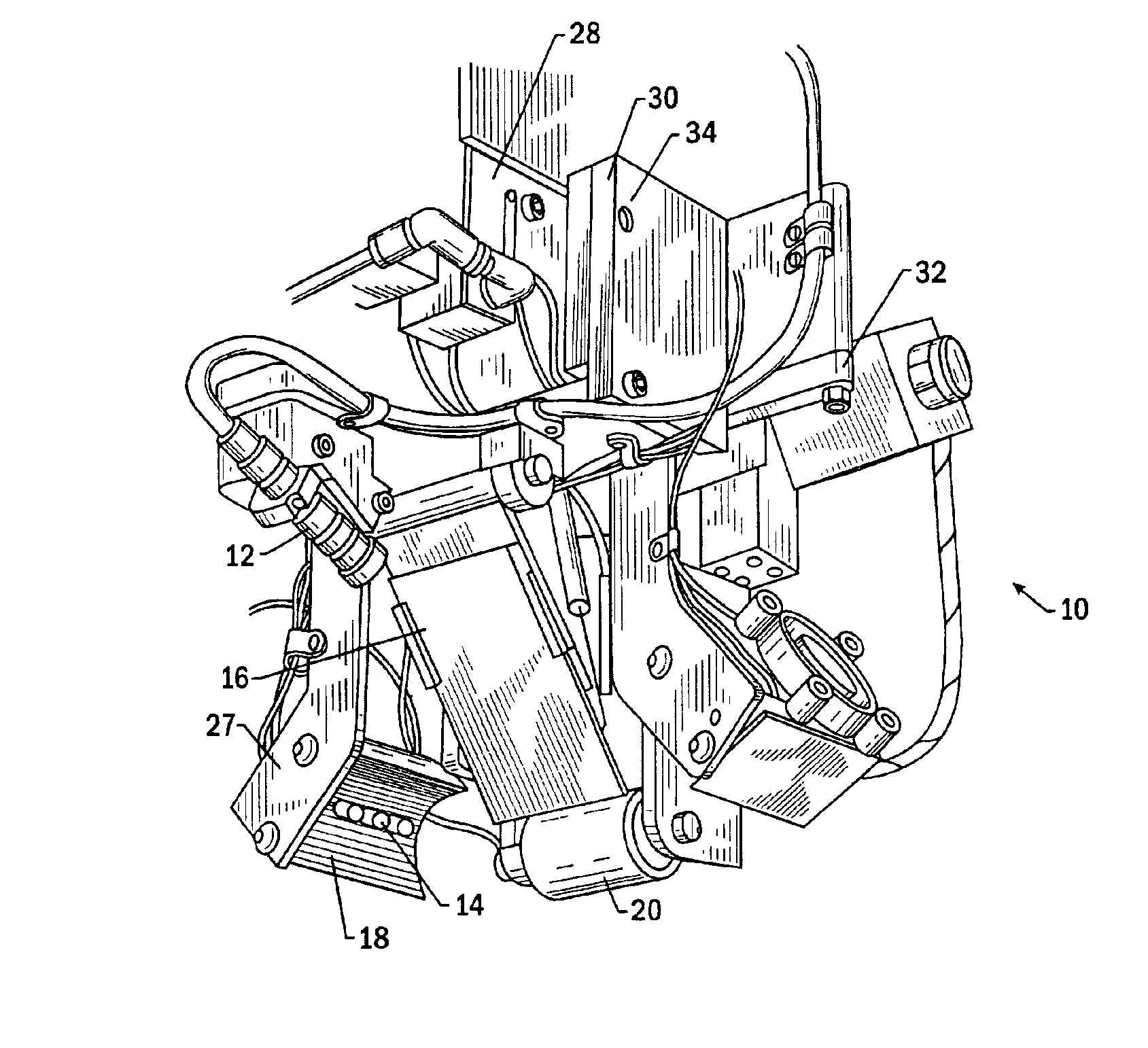
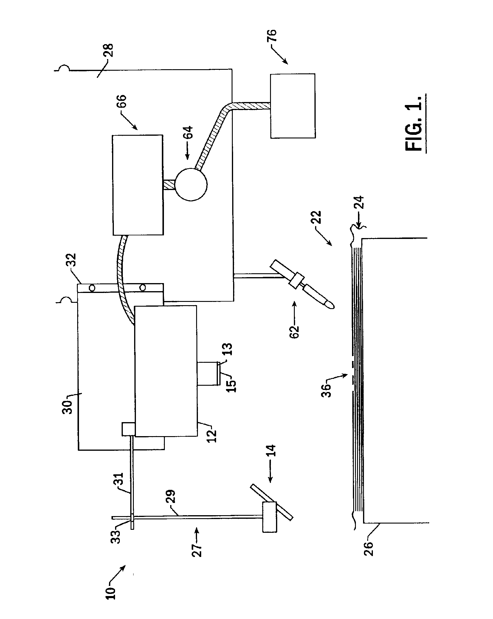
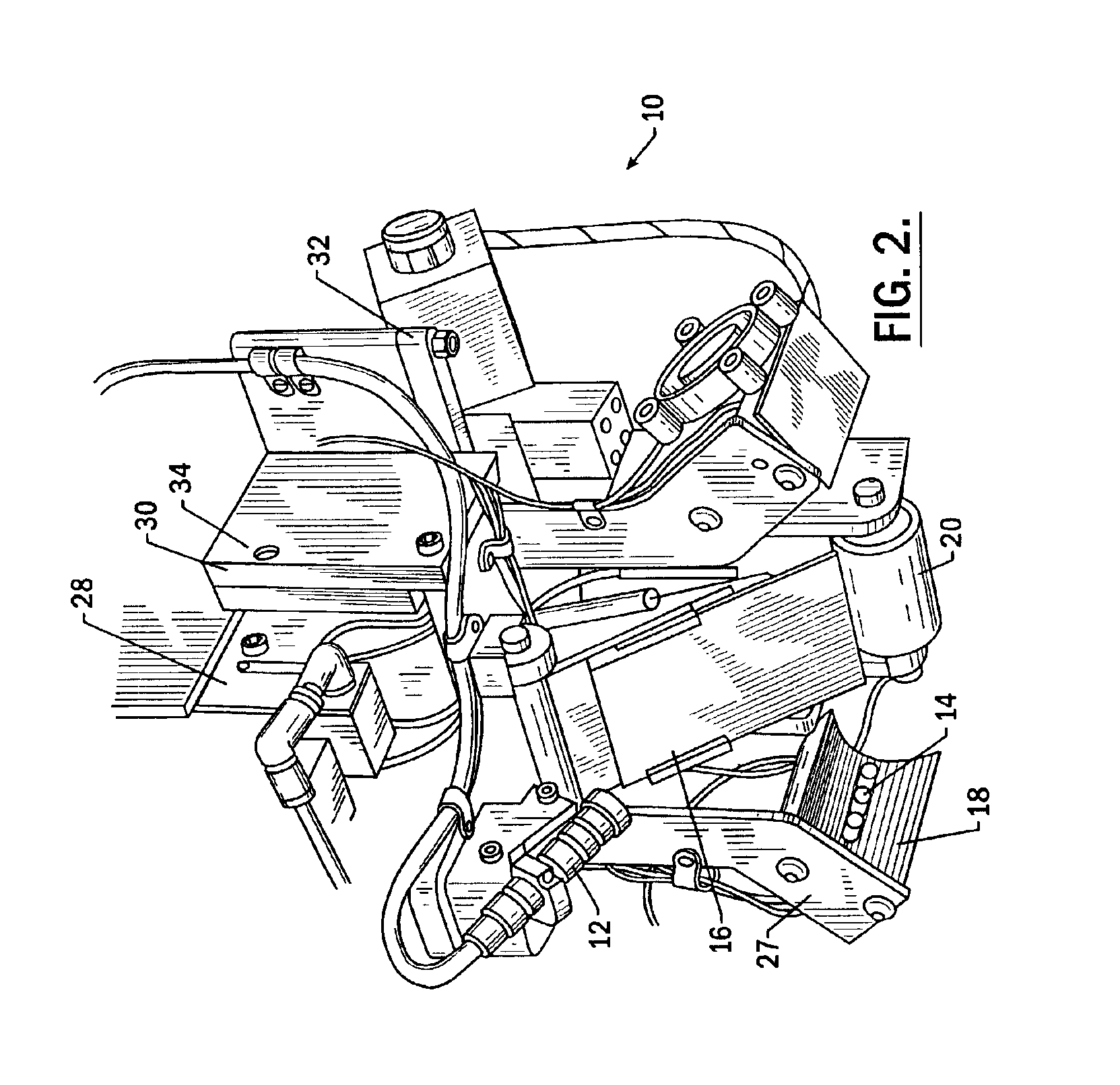
Embodiments of the system for identifying defects in a composite structure according to the present invention are generally referred to as numeral 10 in FIGS. 1 and 2. As shown in FIG. 1, the system 10 is positioned proximate a composite structure 22, which is generally comprised of a plurality of adjacent tows or strips 24 of composite tape. The strips 24 typically include a plurality of fibers embedded in a resin or other material that becomes tacky or flowabl...


PUM

PropertyMeasurementUnit
Dispersion potentialaaaaaaaaaa
Structureaaaaaaaaaa
Reflectionaaaaaaaaaa

Abstract

The present invention provides an improved system for identifying defects in a composite structure by providing a light source such that defects, and in particular dark defects on a dark background and/or light defects on a light background, can be identified by capturing images of the illuminated composite structure. In particular, the improved system for identifying defects in a composite structure may provide a reflective surface, dispersion elements, and multiple and/or moveable light source(s) and/or camera(s) in order to ensure that the most accurate images of any area of the composite structure, even curved or contoured areas, are captured and processed. As a result, the system of the present invention permits the operator to quickly identify and correct defects which would otherwise create structural flaws or inconsistencies that may affect the integrity of the composite structure.

Description

BACKGROUND OF THE INVENTIONThe present invention relates generally to the fabrication of composite structures, and more particularly to systems and methods adapted for locating defects during fabrication of composite structures.Composite structures have been known in the art for many years. Although composite structures can be formed in many different manners, one advantageous technique for forming composite structures is a fiber placement or automated collation process. According to conventional automated collation techniques, one or more ribbons of composite material (also known as composite tows) are laid down on a substrate. The substrate may be a tool or mandrel, but, more conventionally, is formed of one or more underlying layers of composite material that have been previously laid down and compacted. In this regard, conventional fiber placement processes utilize a heat source to assist in compaction of the plies of composite material at a localized nip point. In particular, t...

Claims


Application Information

Patent Timeline
IPC IPC(8): G01N21/88G01N21/95G01N21/86G01N21/84
CPCG01N21/88G01N21/8806G01N2201/0618G01N2021/888G01N2021/8472G01N2201/0634G01N2201/0636
Inventor ENGELBART, ROGER W.WALTERS, CRAIG
Owner THE BOEING CO
Why Eureka
Try Eureka