Image recording method and apparatus with density control

a density control and image technology, applied in the field of image recording methods and equipment, can solve the problems of high cost, complicated control, and difficulty in obtaining density stably

Inactive Publication Date: 2004-11-02
KONICA CORP
View PDF6 Cites 0 Cited by
  • Summary
  • Abstract
  • Description
  • Claims
  • Application Information

AI Technical Summary

Benefits of technology

According to the image recording method, the temperature of the light source varies while the sensitivity of the thermally developed photothermographic imaging material varies, according to the temperature variation. Thereby, the wavelength of the light beam exposed from the light source on the basis of an image signal varies, and the sensitivity of the photothermographic imaging material (the photothermographic imaging material in the forming of the latent image) varies. However, since the wavelength characteristic of the light beam is selected on the basis of the spectral sensitivity characteristic of the photothermographic imaging material, and the former sensitivity variation and the latter sensitivity variation are offset, the density variation of an outputted image caused by the temperature variation can be restrained and density stability can be achieved. Thus, in the image recording method according to the present invention, the variation in characteristic of development of the photothermographic imaging material according to the temperature and the spectral sensitivity characteristic of the photothermographic imaging material depending on the temperature characteristic of the wavelength of the light source are set so that both sensitivity variations will be offset. Thereby, the density variation of the outputted image caused by the temperature variation can be restrained effectively.
According to the image recording method, the sensitivity of the thermally developed photothermographic imaging material becomes large according to a temperature rise. On the other hand, the peak of wavelength of the light beam exposed from the light source on the basis of an image signal varies to the long wavelength side by the temperature rise of the light source according to the above-described temperature rise. Since the peak of the wavelength of the light beam is in the wavelength side longer than the peak of the spectral sensitivity of the photothermographic imaging material, the sensitivity of the photothermographic imaging material to the light beam varied to the long wavelength becomes small. Therefore, since the former sensitivity variation and the latter sensitivity variation of the thermally developable photosensitivity material are offset, the density variation of an outputted image caused by the temperature variation can be restrained, and density stability can be achieved.
According to the image recording apparatus, the temperature of the light source varies while the sensitivity of the photothermographic imaging material thermally developed in the thermal development portion varies, according to the temperature variation. Thereby, the wavelength of the light beam exposed from the light source on the basis of an image signal varies, and the sensitivity of the photothermographic imaging material (the photothermographic imaging material on which the latent image is formed) varies. However, since the wavelength characteristic of the light beam is selected on the basis of the spectral sensitivity characteristic of the photothermographic imaging material, and the former sensitivity variation and the latter sensitivity variation are offset, the density variation of an outputted image caused by the temperature variation can be restrained and density stability can be achieved. Thus, in the image recording apparatus according to the present invention, the variation in characteristic of development of the photothermographic imaging material according to the temperature and the spectral sensitivity characteristic of the photothermographic imaging material depending on the temperature characteristic of the wavelength of the light source are set so that both sensitivity variations will be offset. Thereby, the density variation of the outputted image caused by the temperature variation can be restrained effectively.
According to the image recording apparatus, the sensitivity of the thermally developed photothermographic imaging material becomes large according to a temperature rise in the apparatus. On the other hand, the peak of wavelength of the light beam exposed from the light source on the basis of an image signal varies to the long wavelength side by the temperature rise of the light source according to the temperature rise in the apparatus. Since the peak of the wavelength of the light beam is in the wavelength side longer than the peak of the spectral sensitivity of the photothermographic imaging material, the sensitivity of the photothermographic imaging material to the light beam varied to the long wavelength becomes small. Therefore, since the former sensitivity variation and the latter sensitivity variation of the thermally developable photosensitivity material are offset, the density variation of the outputted image caused by the temperature variation can be restrained, and density stability can be achieved.

Problems solved by technology

Therefore, it is difficult to obtain the density stably.
However, the control is complicated and the cost becomes high, so that it is difficult to obtain ability sufficient as density stability.

Method used


Image

  • Image recording method and apparatus with density control
  • Image recording method and apparatus with density control
  • Image recording method and apparatus with density control

Examples


example

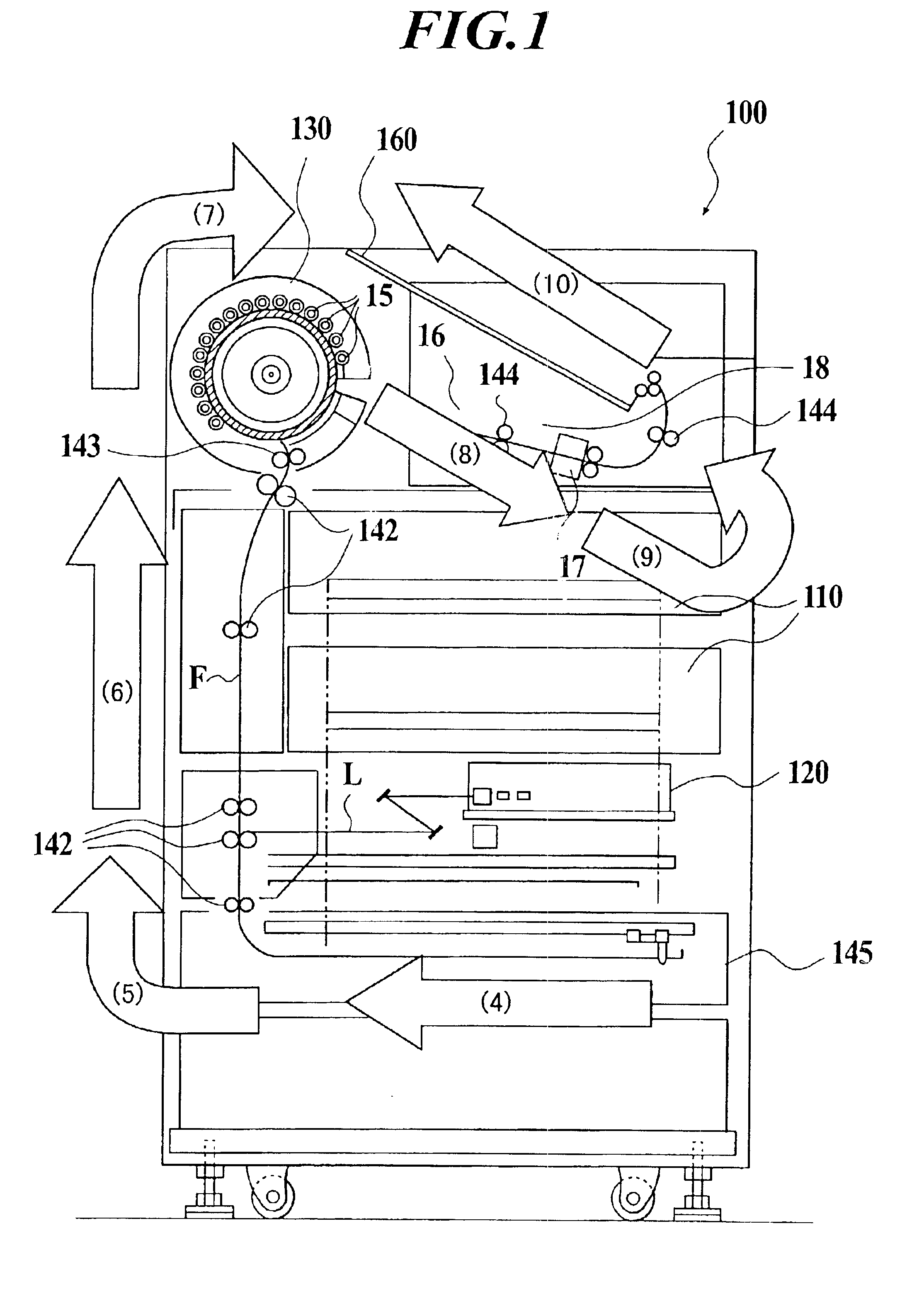
In the above-mentioned embodiment, an apparatus that fulfills all preferred conditions was installed in an environmental test lab. It was heated in a rate of 2.degree. C. / minute from the environmental temperature of 10.degree. C. to 30.degree. C. After the temperature has reached 30.degree. C., it was maintained at a constant temperature for 10 minutes. Then, it was cooled in a rate of 2.degree. C. / minute. After the temperature has reached 10.degree. C., it was maintained at a constant temperature for 10 minutes. While the above-described steps have been repeated, 125 sheets of films for dry image recording SD-P made by Konica Corporation were exposed and thermally developed by this apparatus in an interval of one sheet / minute. As a result, obviously, there was little variation in density in comparison with the variation in density according to the apparatus in the earlier technology.

The present invention is explained by the embodiment as described above. However, the present invent...


PUM

PropertyMeasurementUnit
wavelengthaaaaaaaaaa
constant temperatureaaaaaaaaaa

Abstract

An image recording method includes: forming a latent image on a photothermographic imaging material by exposing a light beam from a light source thereto; and forming a visible image on the photothermographic imaging material on which the latent image is formed by thermally developing it. A wavelength characteristic of the light beam from the light source is selected on a basis of a spectral sensitivity characteristic of the photothermographic imaging material so that a first sensitivity variation of at least one of the thermally developed photothermographic imaging material and the exposed photothermographic imaging material which is before being thermally developed, the first sensitivity variation being caused by a temperature variation, and a second sensitivity variation of the photothermographic imaging material according to a wavelength variation of the light beam from the light source cause by the temperature variation are offset.

Description

1. Field of the InventionThe present invention relates to an image recording method and apparatus for obtaining a visible image by performing thermal development after recording an image on a photothermographic imaging material by irradiating a laser beam to the photothermographic imaging material.2. Description of Related ArtAn image recording apparatus for forming an image on a film by heating the film so as to thermally develop it after forming a latent image by exposing a laser beam to the film of thermally developable silver halide photosensitive material on the basis of an image signal has been known (for example, cf. Japanese Patent Laid-Open Publication No. 2000-292893, Japanese Patent Laid-Open Publication No. 2000-292897 by the applicant or the like, or the like). In such an image recording apparatus, since thermal development treatment is performed, the density of the outputted image varies when the temperature in the inside of the apparatus varies. Therefore, it is diffi...

Claims


Application Information

Patent Timeline
Patent Type & Authority Patents(United States)
IPC IPC(8): B41J2/475G03C1/498G03D13/00G03B27/32G03C5/08
CPCB41J2/4753G03D13/002G03C1/49881
Inventor UMEDA, TOSHIKAZU
Owner KONICA CORP
Why Eureka
Try Eureka