
Through-hole manufacturing method for cylindrical body wall and cylindrical body structure

a manufacturing method and technology for cylindrical bodies, applied in the direction of machines/engines, forging/pressing/hammering apparatus, etc., can solve the problems of long working time, large variations due to individual differences, etc., and achieve the effect of stable flow coefficient, easy manufacturing and easy formation

Active Publication Date: 2010-12-16
MITSUBISHI POWER LTD
View PDF4 Cites 4 Cited by
  • Summary
  • Abstract
  • Description
  • Claims
  • Application Information

AI Technical Summary

Benefits of technology

[0009]Based on such a background, there is a need for a through-hole manufacturing method for a cylindrical body wall and a cylindrical body structure that make it possible to easily and reliably carry out the operation of forming through-holes, such as nozzle holes formed in a fuel injection nozzle, without leaving machining burrs (inner burrs) on the wall of the cylindrical member, without depending on experts.
[0010]The present invention has been conceived in light of the circumstances described above, and an object thereof is to provide a through-hole manufacturing method for a cylindrical body wall and a cylindrical body structure that make it possible to easily and reliably carry out the operation of forming through-holes without leaving machining burrs (inner burrs) on the wall of the cylindrical member, without depending on experts.
[0015]Such a cylindrical body structure includes one pair or a plurality of pairs of through-holes formed in the cylindrical body wall by the tool piercing the cylindrical body wall from the outside of the cylindrical body orthogonally or substantially orthogonally to a cylindrical body axis; and a sealing member configured to seal the through-hole formed by the tool piercing the cylindrical body from the outer wall to the inner wall, wherein the through-hole formed by the tool piercing the cylindrical body from the inner wall to the outer wall is left to serve as a through-hole having no machining burr on the inner wall; therefore, a cylindrical body having through-holes that do not have machining burrs (inner burrs) formed on the inner wall can be easily manufactured.
[0016]In the above-described cylindrical body structure, it is preferable to use the through-holes having no machining burrs on the inner wall as nozzle holes through which a fluid is discharged from the inner wall to the outer wall. In this way, nozzle holes having a stable flow coefficient can be easily formed in the cylindrical body. A preferable cylindrical body in such a case is a fuel injection nozzle of a gas turbine burner.
[0017]With the above-described through-hole manufacturing method for a cylindrical body wall and cylindrical body structure according to the present invention, the operation of forming through-holes, such as nozzle holes formed in a fuel injection nozzle, without leaving machining burrs (inner burrs) on the wall of a cylindrical member can be easily and reliably carried out without depending on experts and intuition. Therefore, significant advantages such as shortening of the working time required for manufacturing the cylindrical member having through-holes, such as the fuel injection nozzle and so on, and product variations due to individual difference etc. can be eliminated, and stability can be achieved.

Problems solved by technology

In other words, manually removing inner burrs is an operation that highly depends on expert workers and that depends on intuition; therefore, a problem that has been pointed out is that the working time is long and variations due to individual differences, etc. are large.

Method used


Image

  • Through-hole manufacturing method for cylindrical body wall and cylindrical body structure
  • Through-hole manufacturing method for cylindrical body wall and cylindrical body structure
  • Through-hole manufacturing method for cylindrical body wall and cylindrical body structure

Examples


Embodiment Construction

[0037]An embodiment of a through-hole manufacturing method for a cylindrical body wall and a cylindrical body structure according to the present invention will be described below with reference to the drawings.

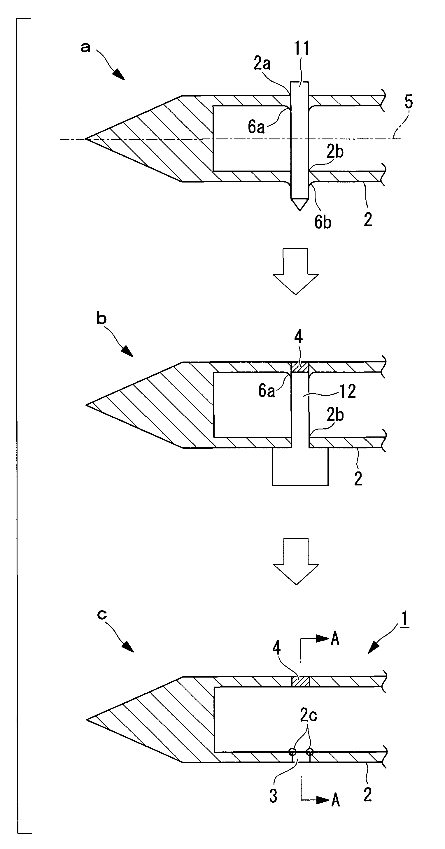
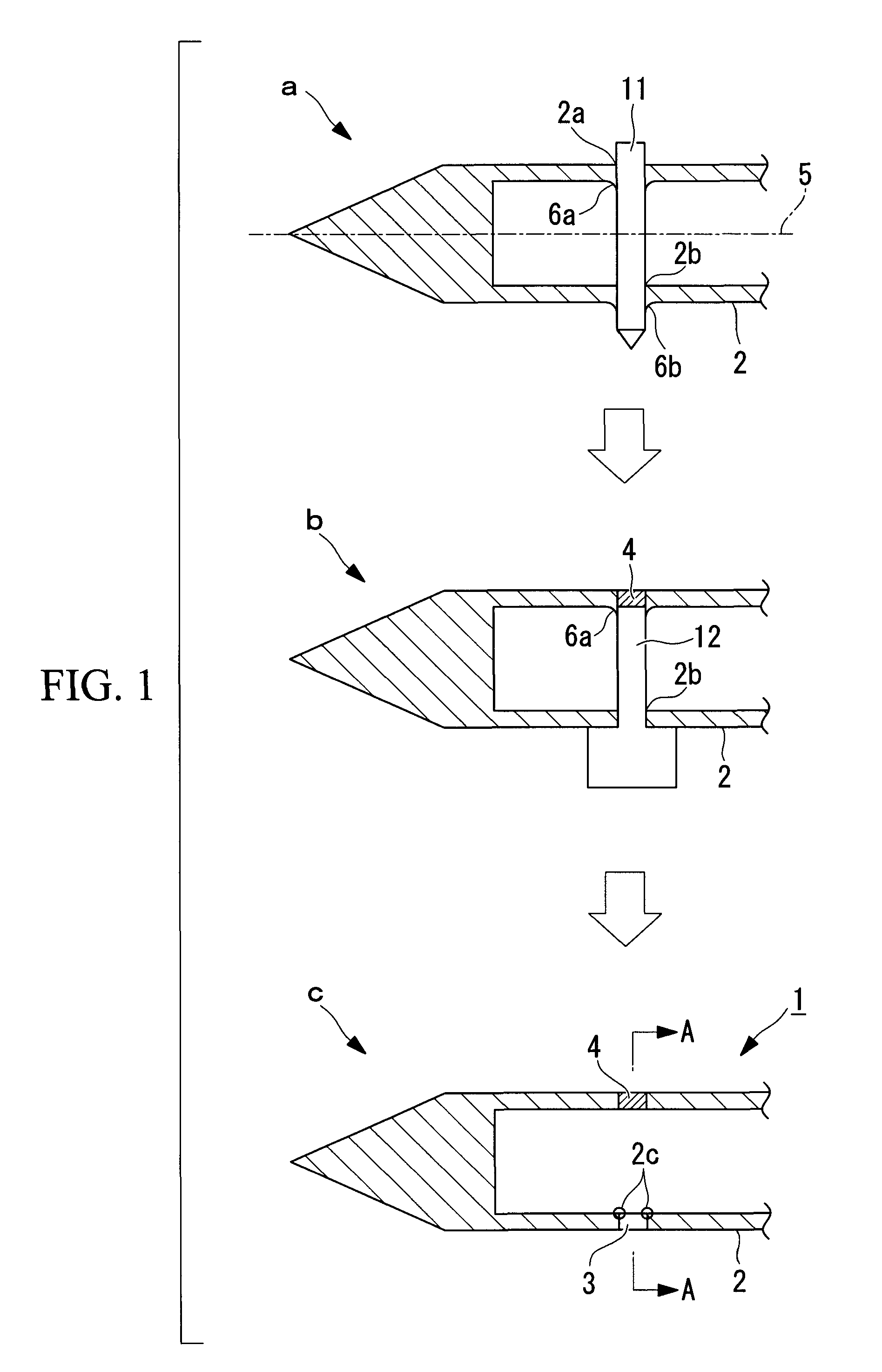
[0038]FIG. 1 is a process diagram illustrating the through-hole manufacturing method for a cylindrical body wall that does not generate machining burrs on the inner wall of the through-holes formed by a tool piercing the cylindrical body wall. In the description below, nozzle holes (through-holes) 3 are formed in a fuel injection nozzle (cylindrical body wall) 1 of a gas turbine burner.

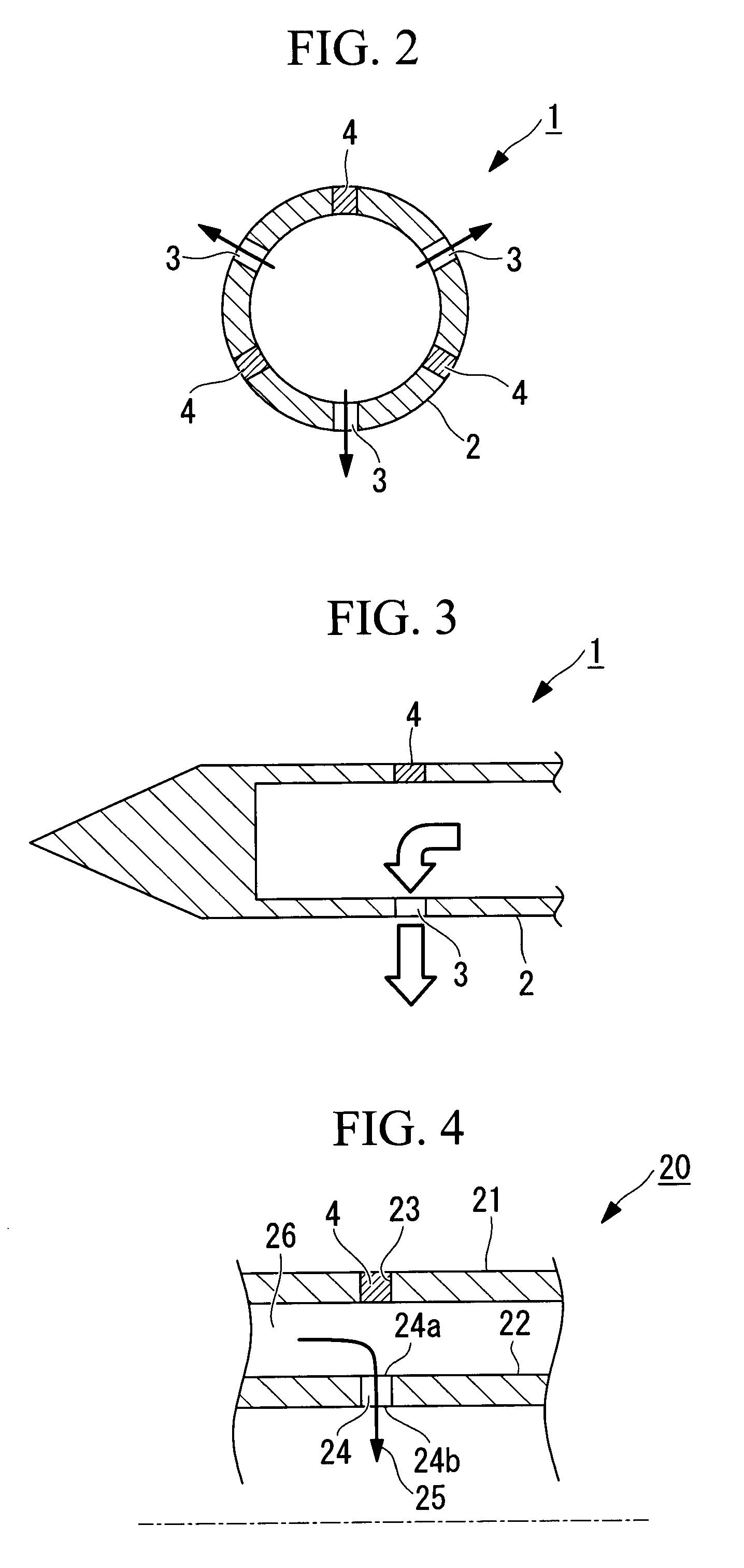
[0039]The fuel injection nozzle 1 employing this manufacturing method has three nozzle holes 3 penetrating the wall of a cylindrical body 2 in a radiating pattern, as shown in FIGS. 2 and 3. The three nozzle holes 3 are arranged in a radiating pattern at a 120-degree pitch in a cross section orthogonal to the axis of the fuel injection nozzle 1. In FIGS. 2 and 3, reference numeral 4 in the drawi...


PUM

PropertyMeasurementUnit
angleaaaaaaaaaa
wall thicknessaaaaaaaaaa

Abstract

There is provided a through-hole manufacturing method for a cylindrical body wall that enables the operation of forming a through-hole without leaving a machining burr on the wall of a cylindrical member to be easily and reliably carried out without depending on experts. A through-hole manufacturing method for a cylindrical body wall in which a machining burr is not formed on inner walls of through holes formed by a tool piercing the wall of a cylindrical body, the method including a hole forming step of forming one pair or a plurality of pairs of the through-holes in the cylindrical body wall by the tool piercing the cylindrical body from the outside orthogonally or substantially orthogonally to a cylindrical body axis of the cylindrical body; and a welding step of sealing the through-hole formed by the tool piercing the cylindrical body from the outer wall to the inner wall by welding using a welding jig made of a material having better heat conductivity than the cylindrical body, wherein the through-hole formed by the tool piercing the cylindrical body from the inner wall to the outer wall is left as a nozzle hole.

Description

TECHNICAL FIELD[0001]The present invention relates to a through-hole manufacturing method for a cylindrical body wall and to a cylindrical body structure that do not leave machining burrs on the inner walls of through-holes, such as fuel injection nozzles of gas turbine burners, for example.BACKGROUND ART[0002]Conventionally, fuel injection nozzles used for gas turbine burners have holes for fuel injection formed penetrating through a cylindrical body wall of a cylindrical member to a hollow section.[0003]A fuel injection nozzle 1 shown in FIG. 6 has nozzle holes 3 that penetrate the wall of a cylindrical body 2 having the shape of a cylinder and through which fluid fuel is injected. The nozzle holes 3 are through-holes formed using a tool, such as a drill, from the outer peripheral side of the cylindrical body 2. When the tool pierces the wall, a machining burr protruding from the inner wall (toward the hollow section) of the cylindrical body 2 is produced. Since the presence of su...

Claims


Application Information

Patent Timeline
Patent Type & Authority Applications(United States)
IPC IPC(8): B21D51/16F02C7/00B21D28/28
CPCB23K28/02Y10T29/49323F02C7/22F02M61/168F02M2200/8069F02M2200/8084F23D2206/10F23D2213/00F23R3/28F05D2240/128F05D2230/232Y10T29/49426Y10T29/49432Y10T29/49405Y10T29/49995B23K2101/006B23K2101/04Y10T29/49316B23P15/16B23K9/04B23P15/00F02C7/00
Inventor MICHINISHI, JUNYAAKAGI, KOICHIKAJIWARA, SHUICHIAKIYAMA, KATSUNORIAOKI, SUNAO
Owner MITSUBISHI POWER LTD
Learn More