Interlocking knockdown furniture with upright locking protrusions

a technology of locking protrusions and knockdown furniture, which is applied in the field of modular furniture items, can solve the problems of insufficient assembly structure, difficult erecting of assembled structures, and inconvenient use of special tools

Inactive Publication Date: 2004-11-09
BART FRANCISCUS P
View PDF30 Cites 6 Cited by
  • Summary
  • Abstract
  • Description
  • Claims
  • Application Information

AI Technical Summary

Benefits of technology

Another basic object is to provide a robust furniture item that can be easily stored and transported.
A similar object is to minimize storage and transportation volume requirements.
Another important object is to provide a similar furniture article of the character described which is lightweight and sturdy.
A still further object is to provide a modular knockdown furniture item such as a table or chair whose components can be sold in an easily assembled kit form.
Another important object is to enable the user to quickly erect a durable and sturdy furniture article without special training.
A similar object is to enable the user to quickly erect a sturdy and durable furniture item without the need for referencing complex manuals or instructions.

Problems solved by technology

The requirement of special tools is especially disadvantageous.
One problem with modular furniture is that sturdy, assembled structures are difficult to erect with parts that are easily assembled and disassembled.
Some devices comprise too many parts, and sometimes tools or special fasteners are required for erection.
Some knockdown devices comprise intricate parts that are too expensive.
Some knockdown articles cannot withstand heavy use, and they will not reliably support heavy loads.
Known devices that do not require fasteners and / or hand tools for assembly or disassembly lack the mechanical durability and dependability required for commercial success.

Method used


Image

  • Interlocking knockdown furniture with upright locking protrusions
  • Interlocking knockdown furniture with upright locking protrusions
  • Interlocking knockdown furniture with upright locking protrusions

Examples


Embodiment Construction

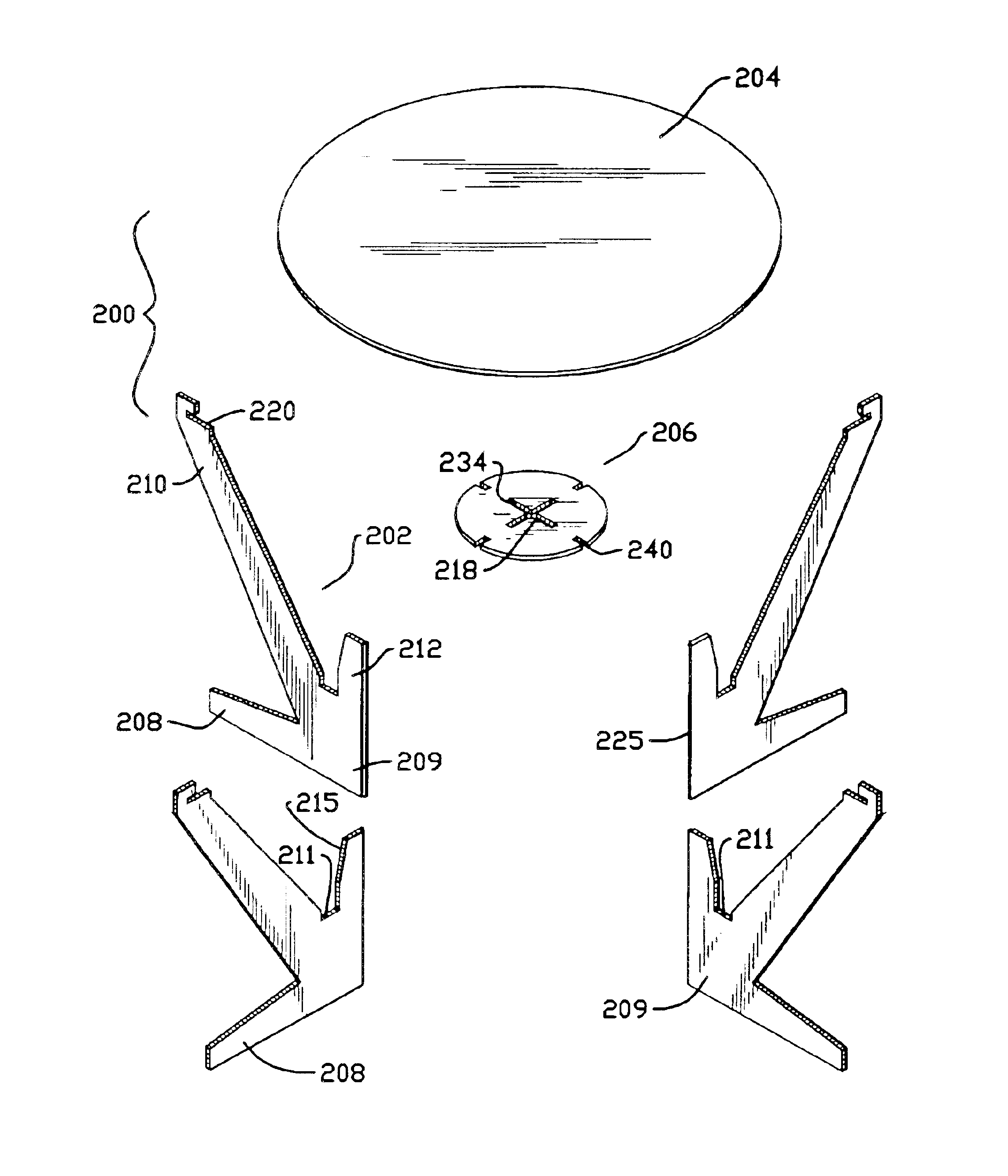
A preferred embodiment is seen in FIGS. 22-26 of the drawings. A furniture item 200, nominally shaped like a table, can also be used as a stool or shelf Item 200 comprises a plurality of similar, flat legs 202, a preferably circular top 204, and a preferably circular lock 206 that has a smaller diameter than tabletop 204. Of course, top 204 and lock 206 can be shaped or dimensioned differently, as will be appreciated by those skilled in the art. In this embodiment, the lock is also sized and configured somewhat like the top 204. Once again, when the aforementioned planar parts are correctly assembled, a strong and dependable structure results. However, the lock 206 is coupled to the legs through a different arrangement. While the indicated structure is slightly different, principles of operation remain largely the same.

Each identical leg 202 comprises a bottom foot 208, an upper arm 210, and a locking protrusion 212 (i.e., FIG. 22), all of which integrally emanate from junction regi...


PUM


Abstract

Knockdown furniture including a table with flat, interlocking, planar parts assembled or disassembled without tools or fasteners. Planar legs oriented in radially, spaced apart, mutually abutting relation upon erection, compressively grasp and support an elevated top. Each leg has a foot touching the ground, an integral, upwardly, outwardly diverging arm for grasping the top, a vertically upright protrusion of gradually decreasing width, and a junction region from which these parts emanate. A planar lock includes slots through which the protrusions pass when the furniture is press-fitted together. Lock notches aligned with the slots concurrently engage the arms. Each protrusion decreases in width, with the outside of each protrusion forming a ramp, and the inside forming an elongated, vertical edge. The wedging action resulting from slot-to-ramp engagement locks the legs together, with the complimentary protrusion edges firmly abutting one another and with the top compressively grasped by the arms.

Description

I. Field of the InventionThe present invention relates generally to modular furniture items. More particularly, my invention relates to portable, knockdown furniture items comprising a plurality of flat, readily transportable parts that can be easily erected or disassembled without special tools.II. Description of the Prior ArtThe prior art recognizes that modular, knockdown furniture items have a variety of useful applications. One advantage of modular construction is that the device parts may be shipped in a flat configuration in disassembled form. The user can then simply fit the parts together to create a piece of furniture. With a variety of parts of different shapes and sizes, the user can create different artistic effects as well as different furniture forms. Once at the application site, the parts should fit together reliably and easily to facilitate erection.Furniture articles that can be folded or disassembled into individual, flat constituent parts can more easily be stor...

Claims


Application Information

Patent Timeline
Patent Type & Authority Patents(United States)
IPC IPC(8): A47B3/12A47B3/00
CPCA47B3/12A47B2200/0032
Inventor BART, FRANCISCUS P.
Owner BART FRANCISCUS P
Why Eureka
Try Eureka