
Method and apparatus relating to the optical zone of an optical element

a technology of optical elements and optical zones, applied in the field of optical zones of optical elements, can solve the problems of affecting the contribution of crystalline lenses to the aberration contribution of ocular aberration, affecting the accuracy of total wavefront aberration, and affecting the accuracy of ocular aberration measuremen

Inactive Publication Date: 2004-11-16
BAUSCH & LOMB INC
View PDF3 Cites 64 Cited by
  • Summary
  • Abstract
  • Description
  • Claims
  • Application Information

AI Technical Summary

Problems solved by technology

This is undesirable for measuring ocular aberrations because pupil dilation is linked to accommodative mechanisms.
This may alter the aberration contribution of the crystalline lens, and the total wavefront aberration may have errors.
These drugs are even less desirable because they directly affect the shape of the crystalline lens.
Extrapolation of Zernike polynomials beyond their normalization radius is undesirable because Zernike polynomials behave wildly outside their normalization radius.
Similar problems are encountered when extrapolation of other types of polynomial expressions are used to describing higher-order aberrations outside of the measurement zone.

Method used


Image

  • Method and apparatus relating to the optical zone of an optical element
  • Method and apparatus relating to the optical zone of an optical element
  • Method and apparatus relating to the optical zone of an optical element

Examples


Embodiment Construction

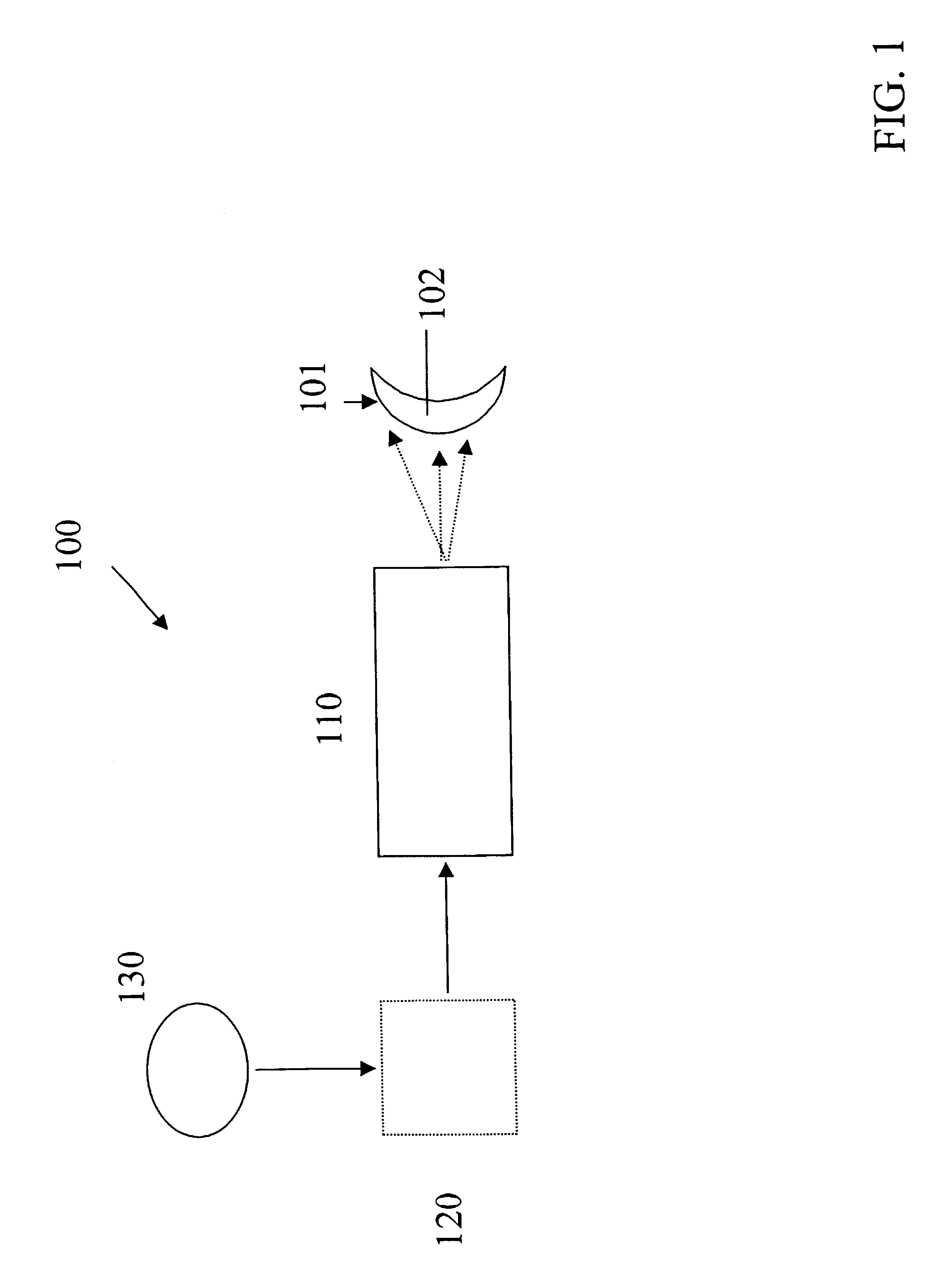
FIG. 1 shows a block diagram of a system 100 for creating an aberration correcting surface 101 on an optical element 102, such as, for example, a custom contact lens, a customized IOL, a corneal inlay, or the cornea of an eye. A device 110, preferably a numerically controlled lathe such as, for example, an Optoform 50 / Variform.RTM. lathe, or a laser such as an ArF excimer laser having a 193 nm output, for example, are suitable for altering the surface 101 of the optical component 102 to create an aberration correcting surface. The device 110 requires an instruction 132 for directing the operation of the device, this instruction being provided in a medium 130 that is readable by the device 110 directly, or alternatively, through a control system 120 shown in dotted lines. It should be understood that the instruction 132 can be encoded software, a minifile, or any other executable form useable by the device 110 and / or the control system 120. The readable medium 130, likewise, will be ...


PUM


Abstract

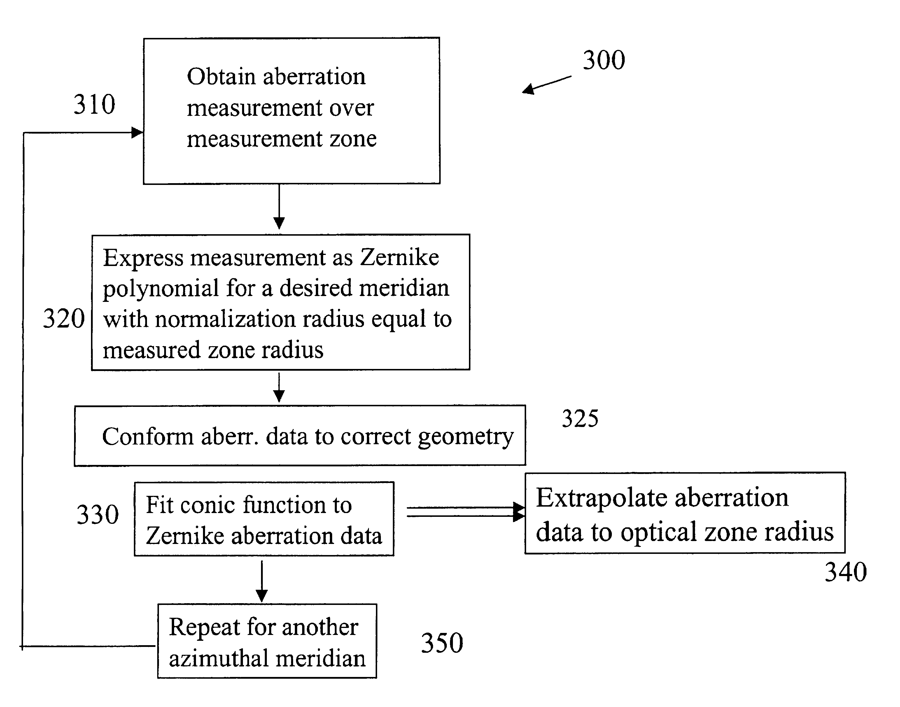
The invention relates to the determination of higher-order aberrations of an optical element over an optical zone that is larger than the typically limited measured zone over which the aberrations are measured. This is accomplished by apparatus, systems, and methods in which, preferably, the Zernike data from an aberration measurement is fit to a conic function. The conic function smoothly and continuously increases or decreases between the measured zone and the optical zone allowing the extrapolated data to accurately determine the aberrations over the optical zone. According to the invention, a plurality of independent conic plus piston sections that vary azimuthally can very accurately describe a wavefront aberration composed of defocus, astigmatism, spherical aberration, secondary astigmatism, and tetrafoil. The description of primary coma and trefoil will not be as good because they vary with the 3<rd >order of the radial component. However, the description error is relatively small. A tilt term can be added to account for the tilt component of the coma and trefoil terms.

Description

1. Field of the InventionThe invention is generally directed to the field of ophthalmic vision correction, and more specifically to a method, a readable medium, and a system related to determining the optical zone associated with higher-order aberration correction provided by a custom contact lens, a custom IOL, a corneal inlay, or refractive laser surgery.2. Description of Related ArtUntil about the beginning of the last decade, vision correction consisted of approximately determining the lower order aberrations of a person's eyes, namely defocus, cylinder (astigmatism) and the cylinder axis, and prescribing spectacle or contact lenses to approximately correct these aberrations.More recently, however, the application of wavefront sensor technology (aberrometers) to the field of ophthalmic vision correction has allowed practitioners to accurately measure the higher-order aberrations of optical systems such as the eye. These higher-order aberrations include secondary astigmatism, sph...

Claims


Application Information

Patent Timeline
Patent Type & Authority Patents(United States)
IPC IPC(8): A61B3/107
CPCA61B3/0025
Inventor ALTMANN, GRIFFITH E.
Owner BAUSCH & LOMB INC
Learn More