Method and Apparatus for Online Contact Lens Evaluation

Inactive Publication Date: 2007-11-29
BAUSCH & LOMB INC
View PDF8 Cites 56 Cited by
  • Summary
  • Abstract
  • Description
  • Claims
  • Application Information

AI Technical Summary

Benefits of technology

[0005] An embodiment of the invention is directed to a specially marked contact lens suited to online, in-vivo measurement of position and orientation. According to an aspect of this embodiment, the lens's posterior or anterior surface, or the lens body, has a light absorbing or scattering pattern of marks in an optical zone region of the lens. The marks are intended to be illuminated by light that is propagating from the retina outward, and which are then imaged by a CCD detector/camera. This illumination technique provides a contrasting bright pupil image with dark appearing marks. The marks do not affect the vision of a person wearing the contact lens. In various aspects of the embodiment, the marks may be molded mar

Problems solved by technology

There are added complications when contact lenses are worn by the patient to improve vision.
It is well known that the position of a contact lens in vivo is not stable.
These aberrations not only include the manifest

Method used


Image

  • Method and Apparatus for Online Contact Lens Evaluation
  • Method and Apparatus for Online Contact Lens Evaluation
  • Method and Apparatus for Online Contact Lens Evaluation

Examples


Embodiment Construction

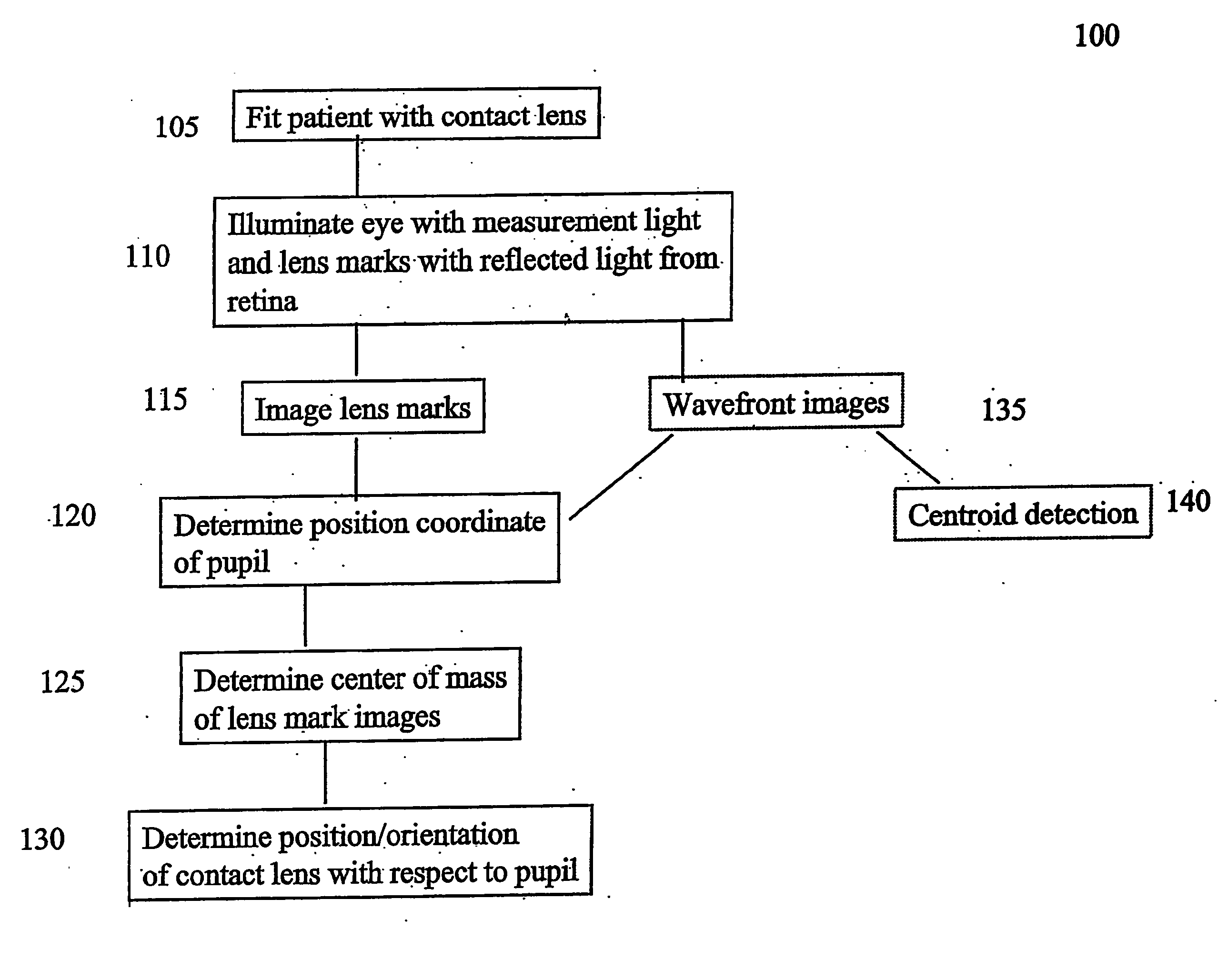
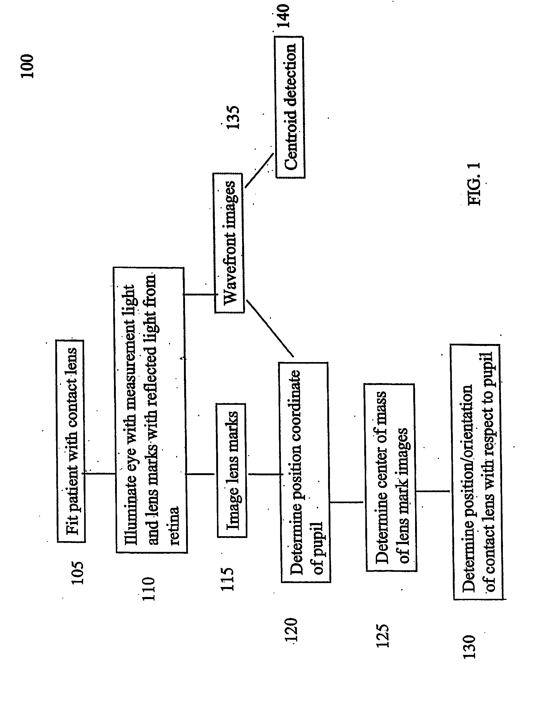
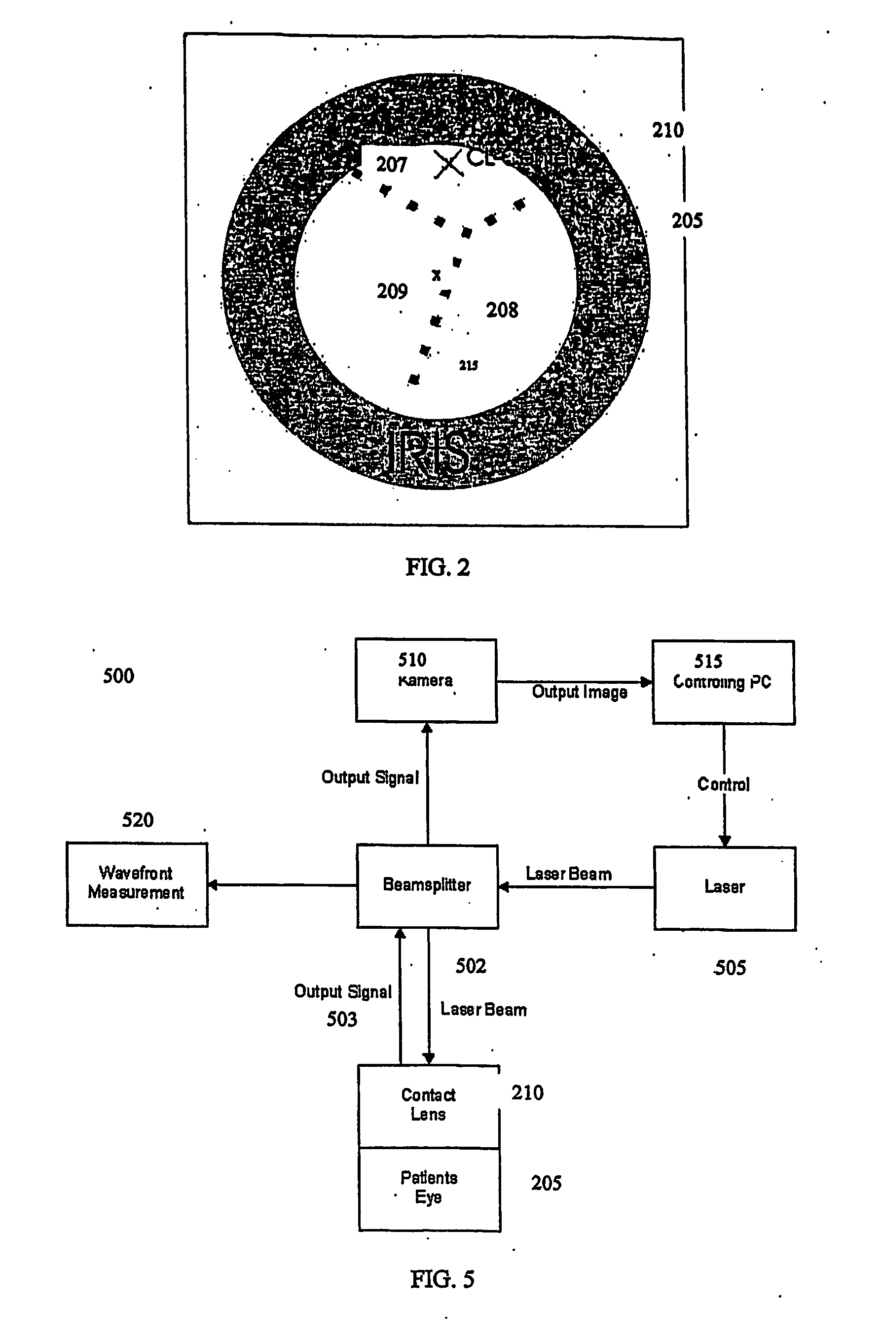
[0042] The term “online” as used herein, refers to measuring and evaluating (and optionally displaying) selected phenomena substantially simultaneously. In the embodied applications, this generally means acquiring a wavefront (lenslet) image, analyzing the wavefront data, and (optionally) displaying the results in a time of less than about 100 ms, and typically less than 40 ms, over a selected time interval of ten's of seconds, typically about 10-20 seconds but in no way so limited. For example, according to an illustrative embodiment, the in-vivo position and orientation of a specially marked contact lens, along with pupil size and position, and a selected second through 9th Zernike-order aberration are determined and displayed at a rate of 25 Hz over a 10 second interval. 250 image pairs comprising pupil and Hartmann-Shack lenslet images are acquired, from which the instantaneously available (approximately 40 ms / image) data indicates how and where the contact lens moves and the ef...


PUM


Abstract

A selectively marked contact lens having, in one aspect, marks in an optical zone region on a surface thereof and, in another aspect, different marks outside an optical zone region of the lens, for an in-vivo lens. With the lens in-vivo, the subject's eye is illuminated and the lens is imaged. A fast algorithm is used to determine the mark coordinates in relation to a measured pupil coordinate to determine position and/or orientation of the contact lens. A wavefront aberration measurement can also be obtained simultaneously with the contact lens position measurement, as well as pupil size. A fast algorithm provides for online measurements; i.e., at a repetition rate of 10 Hz or greater, over a selected time interval. Blinking periods are determined and anomalous lens position and/or wavefront information is discarded. A most frequently occurring wavefront and/or contact lens position/orientation is determined over the selected time interval.

Description

FIELD OF THE INVENTION [0001] Embodiments of the invention are generally related to the applications of ophthalmic wavefront sensing, and more particularly to measuring and evaluating the position and effects of a contact lens in vivo. DESCRIPTION OF THE RELATED ART [0002] The measurement of a person's vision can be accomplished in many ways. The most traditional method involves a visual acuity measurement in which the patient is asked to read variously sized letters on a distant chart while looking through different lens prescriptions provided by the practitioner. The patient's manifest refraction (i.e., spherical power, cylinder power, and axis) is determined by the patient's choice of the test lenses, which provide the clearest vision of the distant eye chart. Shortcomings of this technique are widely recognized. For example, the test lenses are limited to discrete rather than continuous prescription values; visual acuity is substantially the only vision metric that is evaluated;...

Claims


Application Information

Patent Timeline
IPC IPC(8): A61B3/10G02C7/02A61B3/103A61B3/11
CPCG02C7/021G02C7/047G02C7/04G01M11/00
Inventor POLLAND, HANS-JOACHIMSEITZ, STEFANHOHLA, KRISTIANYOUSSEFI, GERHARDHEGELS, ERNSTJANSEN, BIRTESAPPEL, CHRISTOPH
Owner BAUSCH & LOMB INC
Why Eureka
Try Eureka