Moire aberrometer

Inactive Publication Date: 2004-09-30
BAUSCH & LOMB INC
View PDF11 Cites 53 Cited by
  • Summary
  • Abstract
  • Description
  • Claims
  • Application Information

AI Technical Summary

Problems solved by technology

It is no longer adequate to merely measure the topology of the cornea to determine how to best re-shape a person's cornea for vision correction.
The me

Method used


Image

  • Moire aberrometer
  • Moire aberrometer
  • Moire aberrometer

Examples


Embodiment Construction

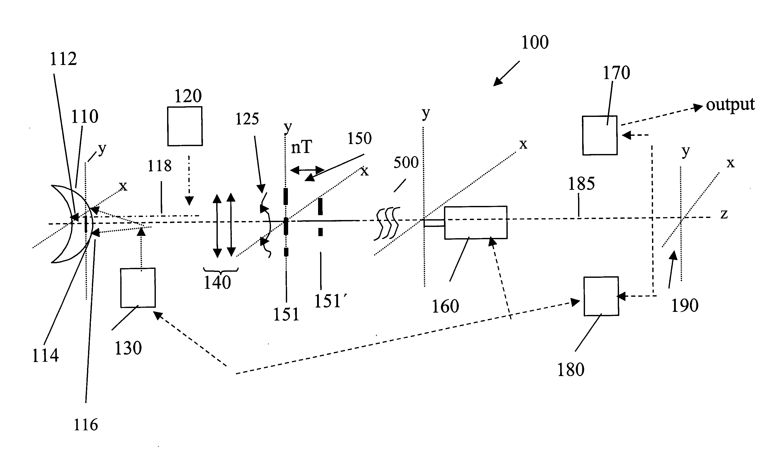
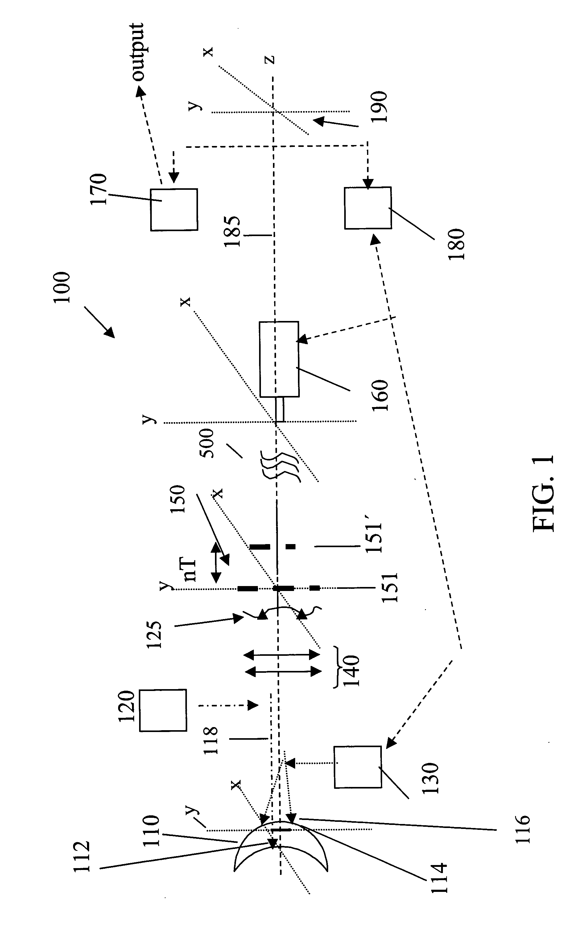
[0019] An embodiment of the moir wavefront sensor apparatus 100 according to the invention is illustrated in FIG. 1. The device, in essence a moir deflectometer, measures and analyzes wavefront aberrations of an optical system 110. Optical systems of interest include living human eyes and test objects for calibration purposes, however, the invention is not limited to measurement of these objects. The system 110 operates as a single pass wavefront measuring system as that term is understood in the art. That is, a point source of light of an appropriate spot diameter is created on a posterior diffuse surface 112 of the optical system; i.e., the retina. The posterior surface 112 will diffusely reflect and scatter the small spot of light through and away from the optical system 110 in the form of a wavefront 125.

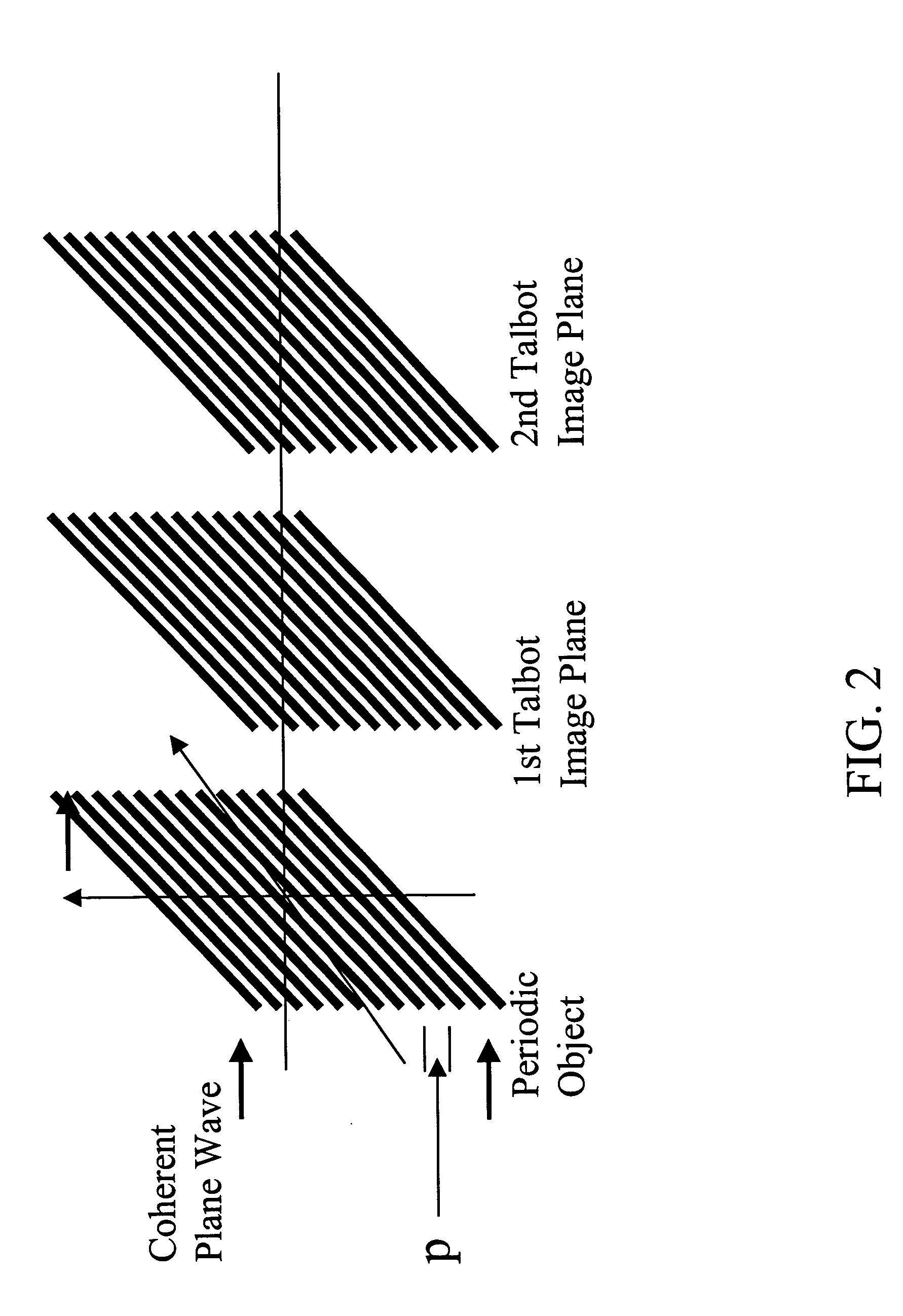
[0020] The fundamental principle of operation of the apparatus disclosed herein is based on Talbot imaging. Talbot imaging is a diffraction phenomenon that occurs with a periodi...


PUM


Abstract

An improved moiré deflectometer device for measuring a wavefront aberration of an optical system includes a light source for illuminating a surface area of the optical system, an optical relay system for directing scattered light to a deflectometer component that converts the wavefront into a moiré fringe pattern, a sensor/camera assembly for imaging and displaying the exit pupil of the optical system and the moire fringe pattern, and a fringe pattern to calculate the wavefront aberration of the optical system, being improved by an illumination source for illuminating the exit pupil of the optical system; and an alignment system cooperating with the illumination source in such a manner to consistently and accurately align a measurement axis of the device to the optical system. An associated method is also disclosed.

Description

[0001] 1. Field of the Invention[0002] The invention is primarily directed to ophthalmic wavefront sensing apparatus and methods and more particularly to a wavefront sensor apparatus and method based upon the principles of moir deflectometry.[0003] 2. Description of Related Art[0004] The measurement of wavefront aberrations of the eye up to the 10.sup.th Zernike order continues to find increasing application in the field of ophthalmology, particularly in relation to refractive surgical procedures such as LASIK, LASEK, PRK, and others. It is no longer adequate to merely measure the topology of the cornea to determine how to best re-shape a person's cornea for vision correction. And while corneal topography systems used in combination with pachymetry devices and ray-tracing techniques can provide a wealth of information about a person's eye and vision problems, aberrometry provides on its own, unique information about the visual defects of the entire optical system of the eye. Wavefro...

Claims


Application Information

Patent Timeline
IPC IPC(8): A61B3/103A61B3/15
CPCA61B3/156A61B3/1015A61B3/103
Inventor EAGAN, BARRY T.
Owner BAUSCH & LOMB INC
Why Eureka
Try Eureka