
Presbyopic vision improvement

a technology of presbyopia and correction, applied in the field of presbyopia, can solve the problems of not fully eliminating residual spherical aberration, and achieve the effects of optimizing the retinal image metric, facilitating the optimal lateral, vertical and rotational placement of the lens, and improving presbyopia

Inactive Publication Date: 2006-10-10
BARCLAYS BANK PLC AS SUCCESSOR AGENT
View PDF15 Cites 55 Cited by
  • Summary
  • Abstract
  • Description
  • Claims
  • Application Information

AI Technical Summary

Benefits of technology

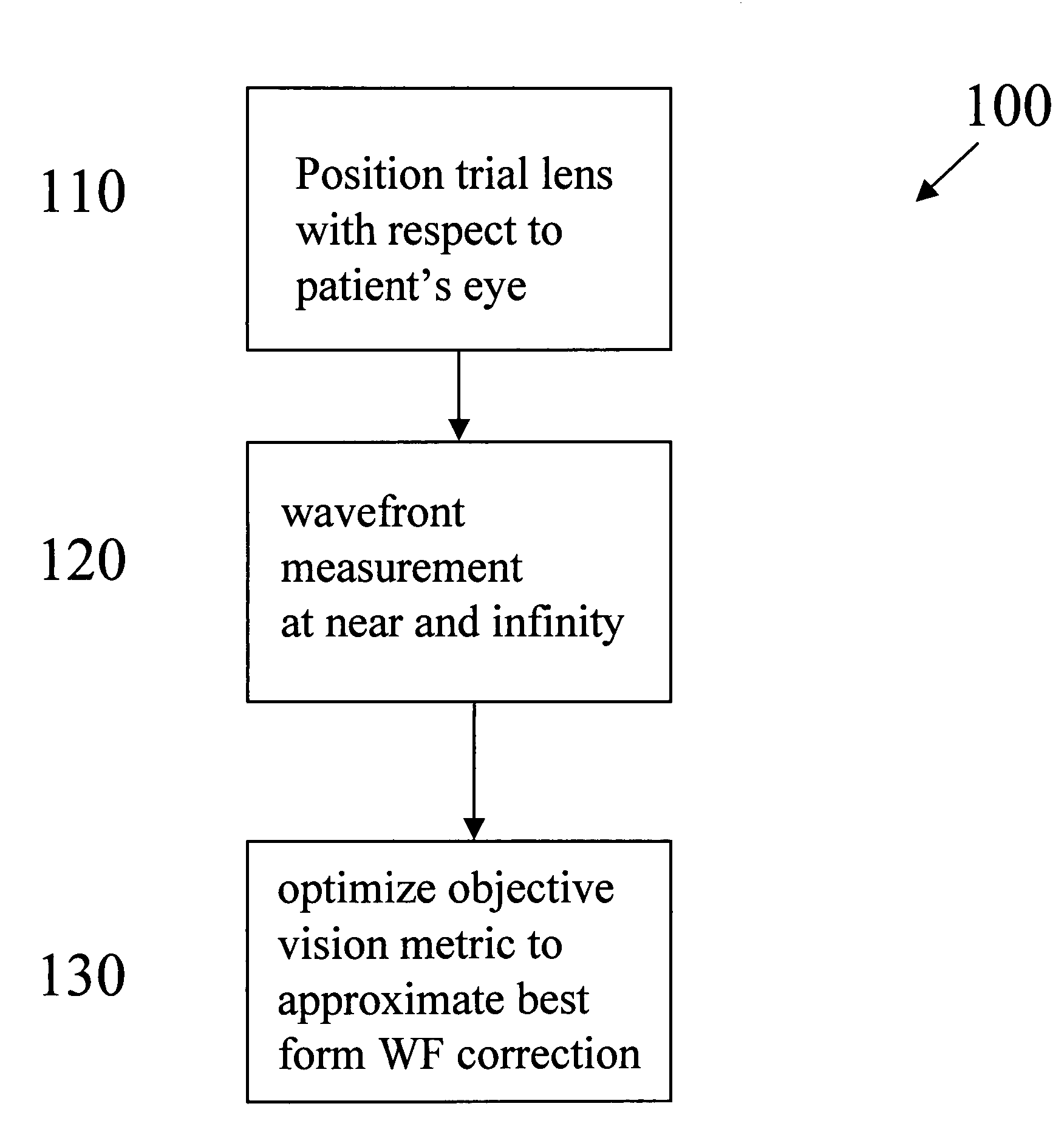
"The invention relates to methods and devices for optimizing presbyopic vision correction, particularly with contact lenses or refractive surgery. The main technical effects of the invention involve using a wavefront sensor in the design and fitting of corrective lenses or refractive surgery to balance various aberrations and improve the objective vision metric of the patient. The method involves positioning a trial lens with a known correction in the patient's eye, measuring the wavefront aberration with the trial lens in position, and using the measurements to approximate the best form wavefront correction for the patient. This allows for the improvement of the retinal image metric and the optimization of presbyopic vision. The invention also includes designing a lens or correction that eliminates or reduces the residual spherical aberration in the patient's eye, and optimizing the depth of field for near vision performance."

Problems solved by technology

Upon retreatment, the surgeon may choose not to fully eliminate the residual spherical aberration.

Method used


Image

  • Presbyopic vision improvement
  • Presbyopic vision improvement
  • Presbyopic vision improvement

Examples


example 1

[0023]This example illustrates the concept that under the ability to manipulate the spherical aberration of an ocular correction, due to the ability to only change rotationally symmetric surfaces or parameters such as, e.g., a contact lens, an IOL, or a broad beam laser, it is more beneficial not to correct all of the spherical aberration when there are significant amounts of non-rotationally symmetric aberrations (e.g., coma, trefoil) present. Patient X had refractive surgery. Her measured post-operative Zernike coefficient values measured with a Zywave® (Bausch & Lomb, Rochester, N.Y.) wavefront sensor were:

[0024]

Z7 Coma0.068Z8 Coma−0.540Z9 (Trefoil)0.103Z10 (Spherical)−0.371Z11 (Spherical)−0.782Z12 (Spherical)−0.308Z13 (Spherical)−0.135Z14 (Spherical)−0.007Z15 (Secondary Coma)−0.183Z16 (Secondary Coma)−0.071Z17 (Secondary Coma)0.021Z18 (Secondary Coma)0.018Z19 (Secondary Coma)0.010Z20 (Secondary Coma)−0.026Z21 (Secondary Spherical)0.023

One can see that there is significant coma a...


PUM


Abstract

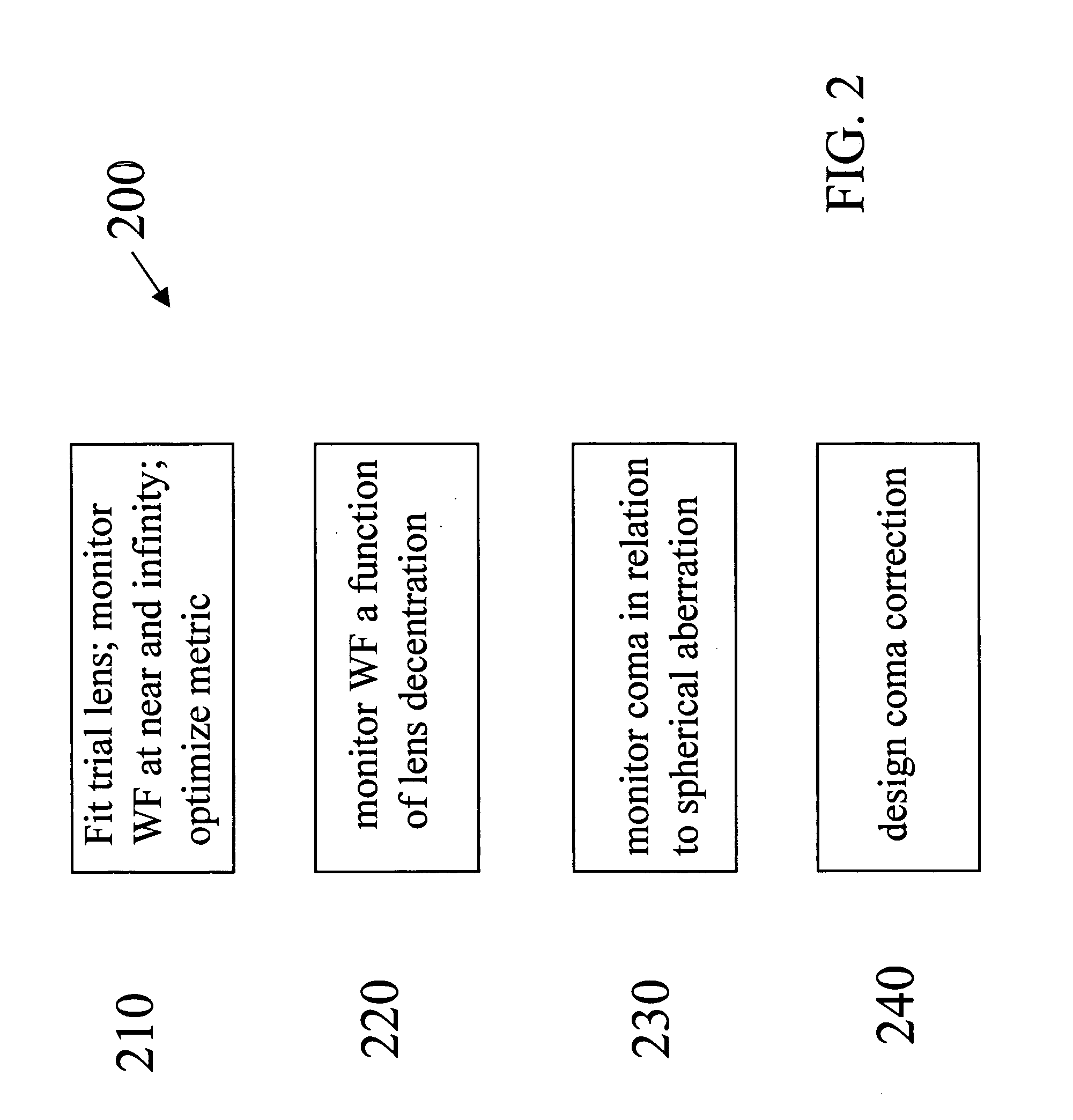
A method of designing a contact lens or other correction for providing presbyopia correction to a patient relies on wavefront aberration measurement data for providing a best form correction. Preferably the correction is in the form of a multifocal translating style alternating vision contact lens or a simultaneous vision style correcting lens. A method for designing a correction for improving a person's vision is directed to correcting higher order aberrations in such a manner that a residual amount of the higher-order rotationally symmetric aberration is greater than a residual amount of the higher-order rotationally asymmetric aberration after the correction. A design method according to the invention is directed to correcting asymmetric higher order aberrations induced by decentering of a multifocal contact lens that has residual spherical aberration which provides increased depth of field.

Description

CROSS-REFERENCE TO RELATED APPLICATIONS[0001]This is a continuation of Provisional Application Ser. No. 60 / 348,192, filed Oct. 19, 2001 and U.S. application Ser. No. 10 / 274,677, filed Oct. 18, 2002, now U.S. Pat. No. 6,808,265 by the same inventors, and claims priority therefrom.BACKGROUND OF THE INVENTION[0002]1. Field of the Invention[0003]The present invention relates generally to the field of presbyopic vision correction and, more particularly, to the use of a wavefront sensor for the measurement, design, fit and dispensing of a vision altering optic or vision correcting procedure to improve presbyopic correction and visual performance.[0004]2. Description of Related Art[0005]A form of age-dependent vision deterioration experienced sooner or later by 100% of the population is called presbyopia, i.e., the inability to accommodate or focus on objects close to the eye. Two well-known methods for dealing with presbyopia include alternating vision style correction and simultaneous vi...

Claims


Application Information

Patent Timeline
Patent Type & Authority Patents(United States)
IPC IPC(8): G02C7/04A61B3/103A61F2/16
CPCA61B3/1015A61F2/16G02C7/028G02C7/042G02C7/043G02C2202/04G02C2202/22A61F2/1618A61F2/1637A61F2240/002A61F2240/008A61F2/14G02C7/047
Inventor COX, IAN G.
Owner BARCLAYS BANK PLC AS SUCCESSOR AGENT
Learn More