Belt-type particleboard press

a belt-type, particleboard technology, applied in the dryer section, dough-sheeters/rolling machines/rolling pins, dryers with progressive movements, etc., can solve the problems of overstressed edge region belt failure, large disadvantage, and exposed rollers at their ends, so as to prolong the service life

Inactive Publication Date: 2004-12-14
SIEMPELKAMP MASCH & ANLAGENBAU GMBH & CO KG
View PDF5 Cites 2 Cited by
  • Summary
  • Abstract
  • Description
  • Claims
  • Application Information

AI Technical Summary

Benefits of technology

Another object is the provision of such an improved belt-type particleboard press which overcomes the above-given disadvantages, that is which ensures adequate protection of the belt-support rollers while at the same time preventing excessive localized stress in the belts.
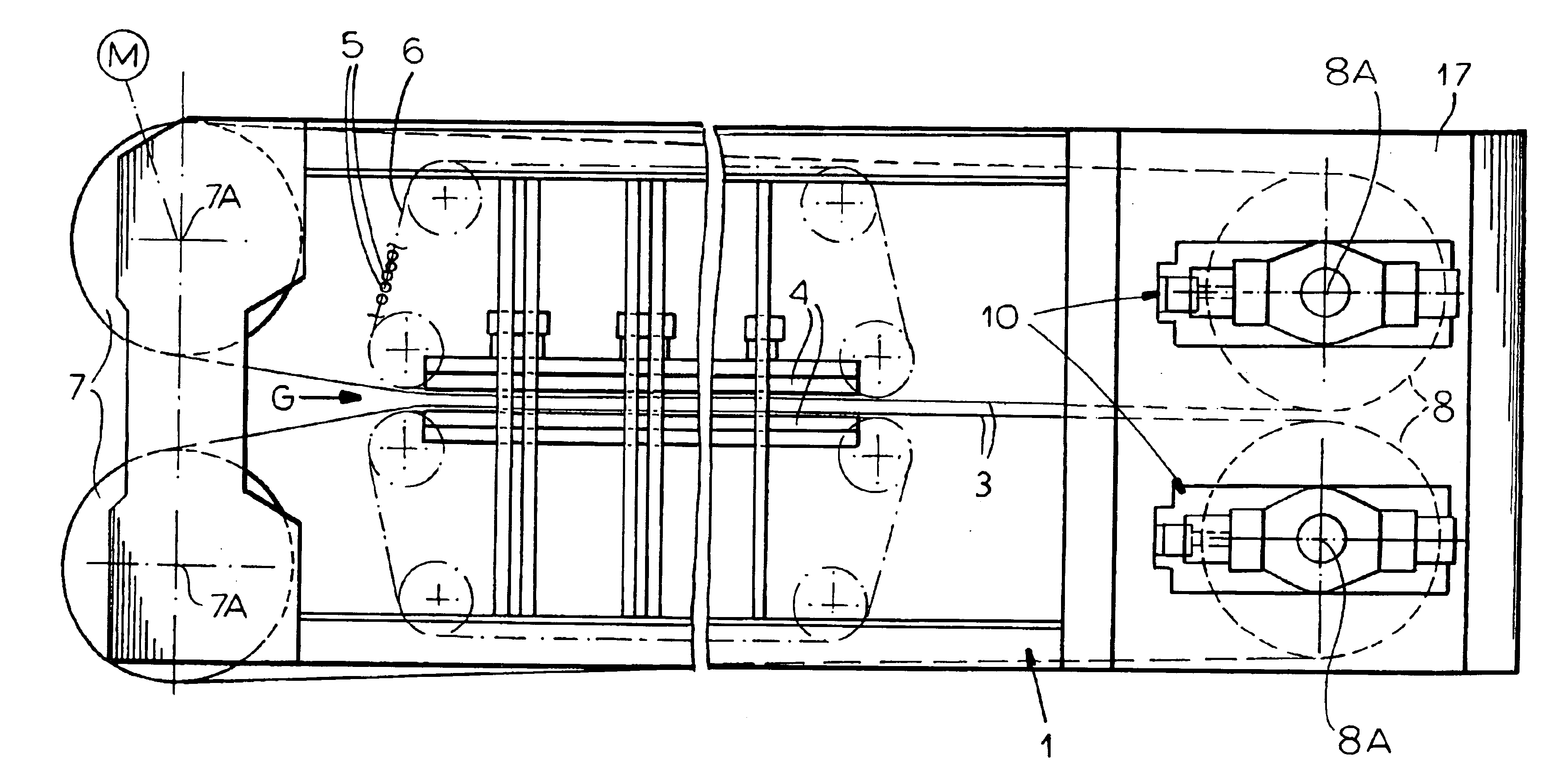
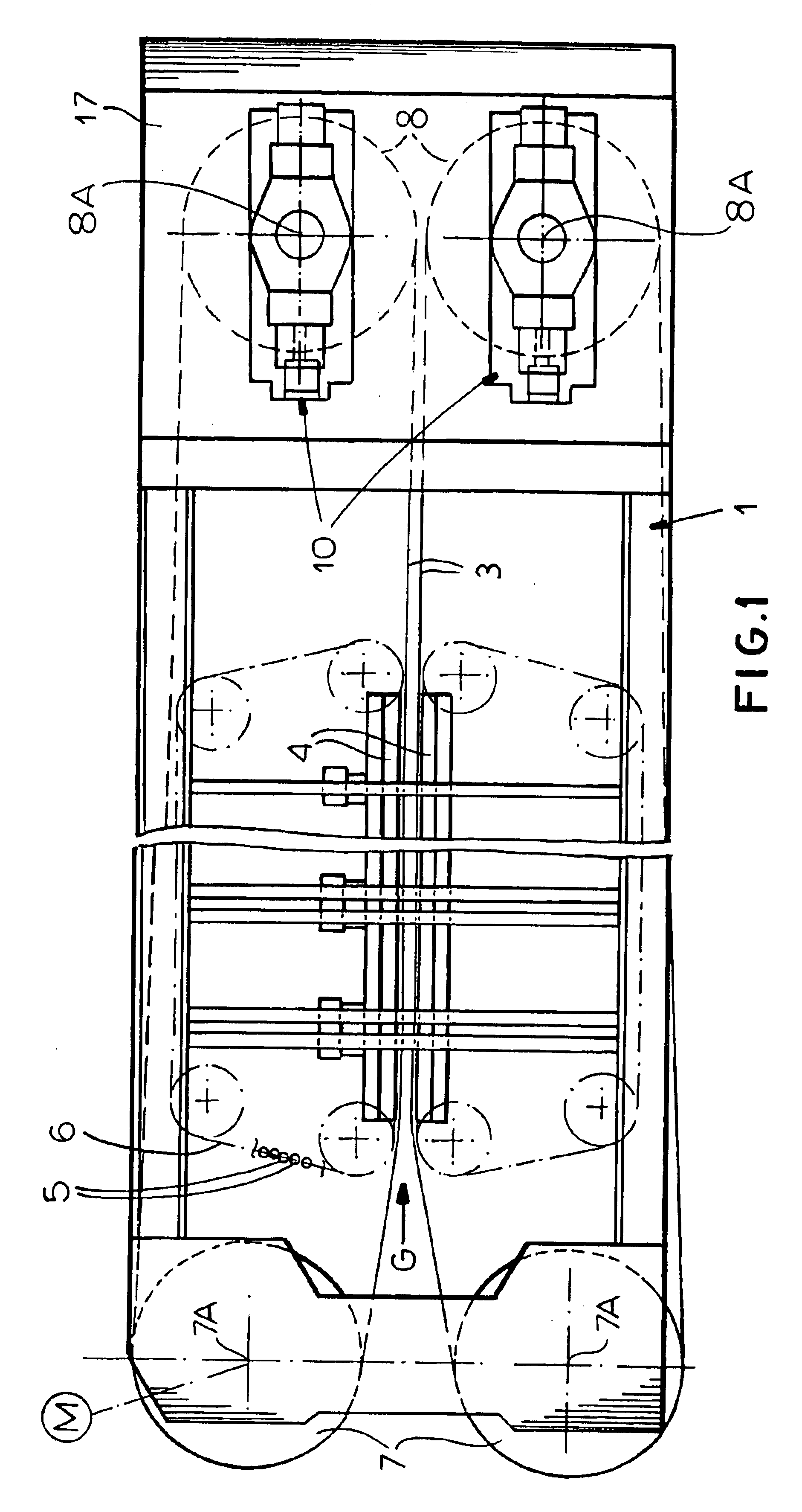
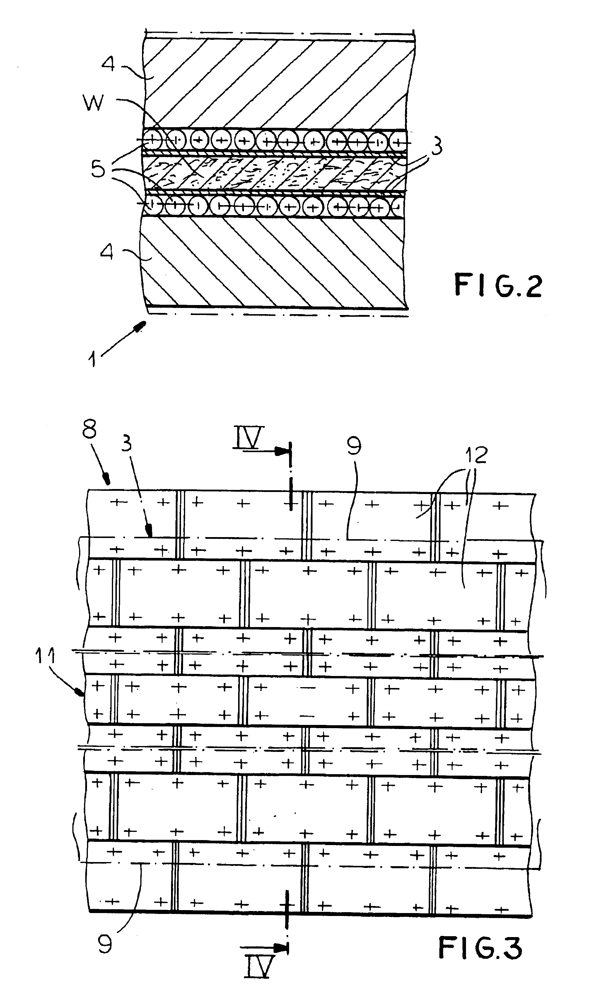
Thus with this system the distance around the drums is in effect shorter at the belt edges so as to accommodate these edges which, as a result of being cooler, are shorter than the central regions of the belts. The belts will therefore be under substantially the same tension over their entire widths, not under greater tension at the edges as in the prior-art systems, so that they will have a much longer service life. Furthermore it is possible to use relatively wide belts, thereby effectively protecting the rollers and drums, something that is extremely important with, for instance, the highly sticky binder used in the production of medium-density-fiber panels.

Problems solved by technology

The result is that the tension in the belts is greater in the effectively shorter edge regions than n the center, leading to premature failure of the belts at the overstressed edge regions.
While this construction ensures that the entire belt is at roughly the same temperature so that the edge regions have the same effective length at the center region, it has the considerable disadvantage that it leaves the rollers exposed at their ends.
Hence the rollers can get fouled so that the press must be cleaned more often.

Method used


Image

  • Belt-type particleboard press
  • Belt-type particleboard press
  • Belt-type particleboard press

Examples


Embodiment Construction

belt has a length l of 65 m and the working stretches in actual contact with the workpiece W have a length of 40 m. There is a temperature differential .DELTA.T of 80.degree. C. between the hot center region 11 and the cooler edge strips 9. This produces in the edge strips 9 a stretch .epsilon. as follows:

.epsilon.=.alpha..multidot..DELTA.T==11.multidot.10.sup. -6.multidot.80.degree.=8.8.multidot.10.sup.-4.

Hence

.epsilon.=.DELTA.l / l.gtoreq..DELTA.l=8.8.multidot.10.sup.-4.multidot.40 m=35 mm.

The drums 7 and 8 have a diameter D of 2950 mm producing a circumference .phi. as follows:

.phi.=.pi. D=9267 mm.

The belts 3 are only looped around half, that is 180.degree., of the drums 7 and 8 so that

.phi. / 2=4633 mm.

Since the colder and shorter belt edges 9 the circumference .phi. of the drums 7 and / or 8 where they contact these edges 9 must be

4633 mm-35 mm=4598 mm.

This corresponds to a diameter of 2972 mm at the formations 12, some 23 mm smaller in diameter, 11.5 mm in radius, than at the drum c...


PUM

PropertyMeasurementUnit
temperatureaaaaaaaaaa
lengthaaaaaaaaaa
lengthaaaaaaaaaa

Abstract

A continuous belt press has upper and lower platens defining a horizontal gap. Upper and lower upstream drums and downstream are rotatable on the frame about respective horizontal drum axes at the upstream and downstream ends of the gap. Upper and lower endless steel belts spanned over the respective upper and lower drums each have a working stretch supported by respective upper and lower sets of rollers on the respective platens. Each belt has a pair of edges projecting transversely past the respective rollers and at least one of the drums of each of the belts has a substantially cylindrical central region of a predetermined central diameter bearing through the respective rollers on the working stretch of the respective belt and a pair of edge formations of smaller diameter than the central-region diameter lying outside the central region and in engagement with the edges of the respective belt.

Description

The present invention relates to a continuous press. More particularly this invention concerns belt-type press used for making wood panels, e.g. particleboard, flakeboard, plywood, chipboard, and the like.A standard belt press has a frame having horizontally extending and vertically spaced upper and lower heated platens defining a horizontally extending gap having an upstream end and a downstream end, vertically spaced upper and lower upstream drums rotatable about respective horizontal axes at the upstream end, vertically spaced upper and lower downstream drums rotatable about respective horizontal axes at the downstream end, and upper and lower endless belts spanned over the respective upper and lower drums and each having a working stretch lying between the platens and a return stretch. Upper and lower sets of rollers engaged between the working stretches and the respective platens can be recirculated as the belts are advanced to move with the working stretches horizontally in a ...

Claims


Application Information

Patent Timeline
Patent Type & Authority Patents(United States)
IPC IPC(8): B30B5/06B30B5/00B27N3/24B27N3/08
CPCB27N3/24B30B5/067B30B5/06
Inventor GAWLITTA, WERNERSEBASTIAN, LOTHARSCHURMANN, KLAUSWEISS, HORST
Owner SIEMPELKAMP MASCH & ANLAGENBAU GMBH & CO KG
Why Eureka
Try Eureka