Milling and clamping device for eccentric upper head flange

A technology of head flange and clamping device, which is applied in the field of machining, can solve the problems of long clamping time, multiple milling machine changes, low efficiency, etc., achieve high uniformity, reduce alignment difficulty, and improve pass rate Effect

Inactive Publication Date: 2016-05-25
四川富临集团成都机床有限责任公司
View PDF5 Cites 0 Cited by
  • Summary
  • Abstract
  • Description
  • Claims
  • Application Information

AI Technical Summary

Problems solved by technology

[0004] The purpose of the present invention is to provide a milling and clamping device for eccentric upper head flanges, which solves the problems of long clamping time, low efficiency and low yield in the current processing technology, so as to improve production efficiency and improve the quality of finished products. purpose of rate
The present invention is a core device proposed by the applicant based on a new process. The applicant found in many years of processing technology that the structure of the upper head flange is rather special, and the position of the groove on the end surface can be changed, but the groove The distance between a cylindrical blind hole at the end and the axis of the flange is fixed. In order to solve the problem of changing the milling machine many times in the existing processing technology, the applicant found after years of research that the blind hole at the end of the groove is the Datum, multiple positions can be processed at one time. First, a positioning plate is installed on the processing table of the milling machine through locking bolts. A set of arc-shaped side walls and eccentric positioning pins are arranged on the positioning plate. The side wall of the cylinder constitutes the outer circle of the cylinder, and the gap between the two arc-shaped side walls is formed. This gap plays an important role. After the sealing plate is put in, the sealing plate can be adjusted and rotated from the side of the gap. It is conducive to quick alignment and positioning. This outer circle is used as the installation reference of the processed sealing plate. When using it, firstly process the end face of the blank, and after processing a qualified end face, mill a groove on the other end face to process the processed One side of the groove is placed on the positioning plate downwards, and the sealing plate is rotated so that the positioning pin is inserted into the blind hole of the groove. At this time, the sealing plate no longer rotates. A conical surface, the conical surface plays a guiding role when putting in the sealing plate, which is convenient for quickly putting in the sealing plate, thereby increasing the speed of clamping; after positioning is completed, the solenoid valve is used as a switch to drive the cylinder, and the cylinder drives the pressure head to act On the sealing plate, press the sealing plate downward, and the sealing plate is fixed under the cooperation of the side wall, the positioning pin, and the pressure head. At this time, the axis hole, four through holes, and strip-shaped holes can be completed on a milling machine. Hole processing, in the processing process, the sealing plate is only clamped once, which improves the processing efficiency, and the position is fixed, it is easy to clamp, reduces the difficulty of alignment, avoids the inaccurate shape of the clamping, and at the same time a reference as the side The processing standards of the wall, four through holes, and strip holes maintain a high degree of uniformity, improve the qualified rate of finished products, and increase the qualified rate of finished products to more than 97%

Method used


Image

  • Milling and clamping device for eccentric upper head flange
  • Milling and clamping device for eccentric upper head flange

Examples


Embodiment

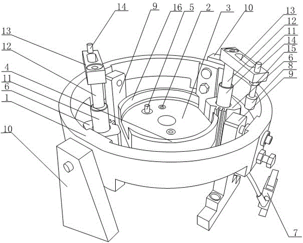
[0022] Such as figure 2 As shown, a milling and clamping device for an eccentric upper head flange according to the present invention includes a positioning ring 1, the positioning ring 1 is in the shape of a ring, and a pair of inner columns 9 are installed on the inner side of the positioning ring 1, and the outer side of the positioning ring 1 An outer column 10 is installed, and the inner column 9 and the outer column 10 are evenly arranged on the positioning ring 1, and the connecting line of the inner column 9 and the connecting line of the outer column 10 are basically vertically distributed, and the positioning ring 1 passes through the inner column 9 and the outer column. 10 is installed on a milling machine, and a cylinder 6 corresponding to the outer column 10 is installed on the inner side of the positioning ring 1. The cylinder 6 is a double-channel cylinder, and the outer channel drives the rotating shaft 11 to rotate, and the inner channel drives the push rod 12...


PUM


Abstract

The invention discloses a hole-milling clamping device for an eccentric upper sealing head flange. The hole-milling clamping device comprises a positioning ring, a positioning disc, air cylinders, electromagnetic valves and pressing heads, a set of circular-arc-shaped side walls and an eccentric positioning pin are arranged on the positioning disc, the circular-arc-shaped side walls form a cylindrical excircle, the inner-side surface of each circular-arc-shaped side wall and an end-portion plane are connected through a bevel, two bevels form a conical face, and the air cylinders extend and contract to drive the pressing heads to press or release a workpiece. By utilizing the hole-milling clamping device, processing of an axis hole, four through holes and a strip-shaped hole can be completed on a milling machine, and a sealing plate is clamped only once during processing, so that processing efficiency is improved; the sealing plate is fixed in position and quite easy to clamp, so that aligning difficulty is lowered, and inaccuracy in clamping is avoided; a reference is taken as a processing reference of the side walls, the four through holes and the strip-shaped hole, so that high uniformity is maintained, qualification rate of finished products is increased, and the finished product qualification rate is increased to be more than 97%.

Description

technical field [0001] The invention relates to a machined one, in particular to a milling and clamping device for an eccentric upper head flange. Background technique [0002] The eccentric upper head flange is a special flange in the pipeline circulation industry, as attached figure 1 As shown, it includes a circular sealing plate 101, an axis hole 102 is opened on the axis of the circular sealing plate 101, and an axis sleeve 103 is installed on the axis hole 102, and a Four through-holes 106 distributed symmetrically around the axis are used to pass through and fix the measurement signal terminals, and arc-shaped strip holes 104 are arranged around the sealing plate 101 for the installation of seals An irregular groove 105 is recessed and formed on the sealing plate 101 for installing the signal measuring block, and its shape matches it. [0003] At present, the processing technology of the eccentric upper head flange is as follows: firstly, the center hole is drilled ...

Claims


Application Information

Patent Timeline
Patent Type & Authority Patents(China)
IPC IPC(8): B23Q3/08
CPCB23Q3/062B23Q3/08B23Q2703/04B23Q2703/10
Inventor 王亮李章文
Owner 四川富临集团成都机床有限责任公司
Why Eureka
Try Eureka